
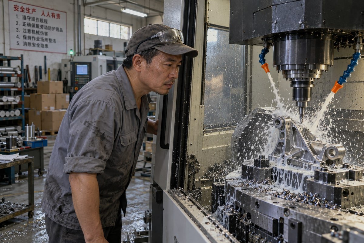
A customer once sent us a bracket drawing with ±0.01 mm bores and one note: last supplier drifted in batch three NADCAP-accredited special processes 1. That fear shapes aerospace CNC machining in our shop.
CNC machining supports the aerospace industry by turning CAD models into repeatable flight hardware with tight dimensional tolerances, machining difficult alloys like titanium and Inconel, producing complex 5-axis geometries, and delivering traceable quality from prototypes to production runs.
That bold answer is the short version. The longer version is where buyers actually get burned. Tolerance, material, geometry, and paperwork each hide a trap. I will walk through all four below, in the order a sourcing manager usually asks about them.
What Precision Tolerances Can I Expect for Aerospace CNC Machined Parts?
A German purchasing manager asked me last year whether ±0.005 mm on a titanium housing 2 was realistic. My honest answer was: on some features, yes; on every feature, no.
Aerospace CNC machined parts commonly hold tight dimensional tolerances of ±0.01 mm, with ±0.005 mm or about ±0.001 inch achievable on critical bores and mating faces. Actual results depend on material, geometry, machine condition, thermal control, workholding, and the inspection method used.
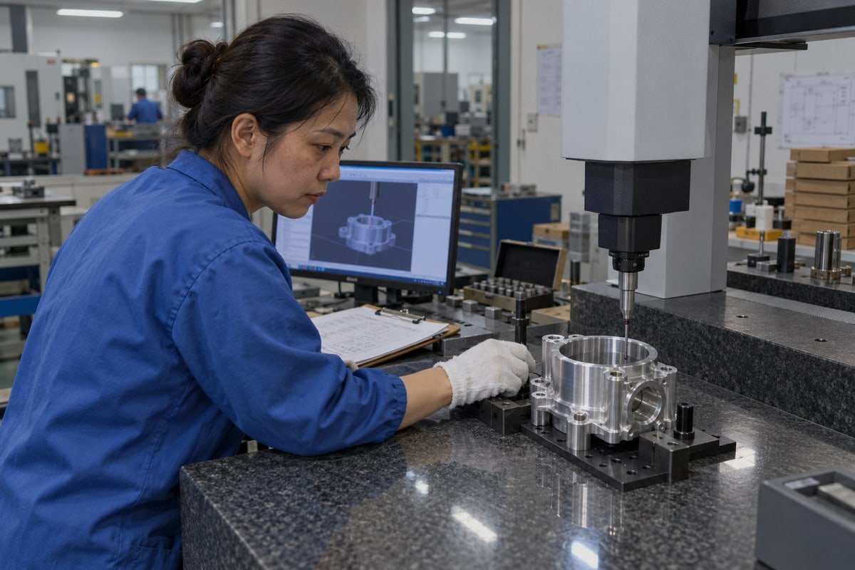
Micron-level precision is a real capability in aerospace CNC machining. But it is a capability claim, not a universal specification. When a supplier says "we hold ±0.001 inch," the right follow-up question is "on which feature, in which material, and measured how?"
Tolerance Is a Feature-Level Question
A single aerospace part rarely has one tolerance. A landing gear fitting might have a bearing bore at ±0.005 mm, a flange face at ±0.02 mm, and a drain hole at ±0.1 mm. Our 3-axis, 4-axis, and 5-axis mills reach 0.01–0.005 mm on suitable features. The table below shows what I quote in practice.
| Feature Type | Realistic Tolerance Band | Main Risk Factor |
|---|---|---|
| Reamed or bored precision holes | ±0.005 mm | Tool deflection, thermal growth |
| Mating faces and sealing surfaces | ±0.01 mm | Clamping distortion, flatness |
| Thin-wall pockets (aluminum) | ±0.02 mm | Residual stress, chatter |
| Curved aerodynamic surfaces (5-axis) | ±0.02–0.05 mm profile | CAM accuracy, machine kinematics |
| Threads and non-critical holes | Standard class fits | Burrs, tap wear |
Why Ordinary Shops Struggle to Repeat It
Here is the personal insight that drives how we run our line. Aerospace work demands three things at once: tight tolerance, surface integrity, and dimensional stability over time. Many general machine shops can hit one of them on a first sample. Holding all three across a batch is where they fail. Surface integrity is not the same as dimensional accuracy. A bore can measure perfectly and still carry a work-hardened layer or micro-cracks that shorten fatigue life. Dimensional stability means the part still measures the same after stress relief, after shipping, and after a month on a shelf.
What We Control to Stay Inside the Band
On our high-speed machining centers we probe the workpiece in-process, so drift shows up mid-batch, not at final inspection. We stress-relieve aluminum before finishing passes on thin walls. We run first-article inspection on the CMM before releasing any batch. And we tell customers plainly when a drawing tolerance exceeds what a feature can hold, rather than promising it and failing later.
Which Materials Are Best Suited for My Aerospace CNC Machining Projects?
Every quote for a titanium bracket forces the same trade-off on our side: slower cutting speeds and faster tool wear against strength-to-weight that aluminum simply cannot match.
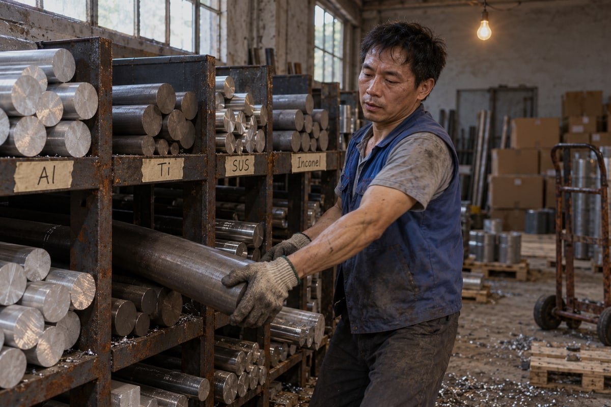
The best aerospace CNC machining materials are aluminum alloys for lightweight structural parts, titanium alloys for high strength-to-weight and corrosion resistance, nickel-based superalloys like Inconel for hot engine sections, steels for landing gear and high-load fittings, and engineering plastics or composites for housings and panels.
Material choice drives cost, lead time, and scrap rate more than any other single decision. Here is how I compare the main families when a customer sends a drawing.
| Material Family | Typical Aerospace Use | Machinability | Main Machining Challenge |
|---|---|---|---|
| Aluminum (6061, 7075) | Wing ribs, brackets, avionics housings | Excellent | Thin-wall distortion, residual stress |
| Titanium (Ti-6Al-4V) | Engine mounts, fittings, fasteners | Difficult | Poor heat conduction, tool wear |
| Inconel 718 and other superalloys | Turbine and combustion hardware | Very difficult | Work hardening, heat at the cutting edge |
| Stainless and alloy steels | Landing gear, actuators, pins | Moderate | Varies by grade and heat treatment |
| PEEK, POM, PPSU | Insulators, cabin fittings, seals | Good | Thermal expansion, burrs |
| Carbon-fiber composites | Panels, fairings | Special tooling | Delamination, fiber pullout, dust |
Titanium and Inconel: Where Tool Life Decides the Quote
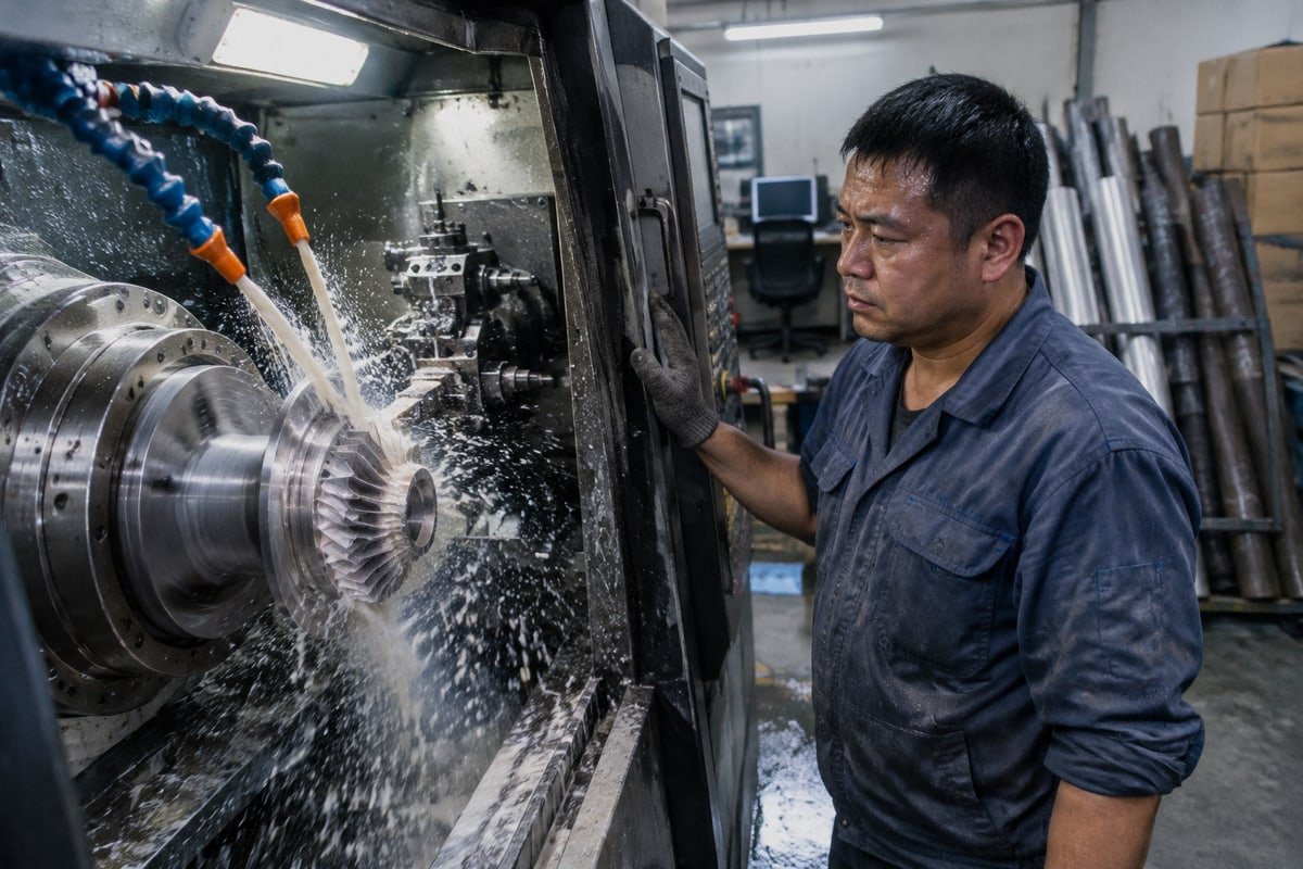
Titanium alloy fabrication is routine for us, but it is never fast. Titanium keeps its strength at cutting temperature and dumps heat into the tool instead of the chip. So we use rigid fixtures, sharp coated carbide, flood coolant, and conservative engagement. Inconel machining is harder again. The material work-hardens under a dull edge, which is why cryogenic machining with liquid nitrogen is gaining attention for heat-resistant superalloys. It keeps the cutting zone cold and limits that hardening. Those engine-section jobs for aircraft engine components 3 are where surface integrity matters most, because fatigue cracks start at the surface.
Composites Are Not Metal Billets
A buyer once assumed trimming a carbon-fiber panel was "just aluminum with different feeds." It is not. Composites need diamond-coated tools, dust extraction, and backing support to avoid delamination. For brittle ceramic matrix composites, ultrasonic-assisted machining is used to reduce edge chipping. We are clear with customers about which composite work we handle in-house and which we do not.
The Buy-to-Fly Objection
Buyers often push back: "Machining a 40 kg billet into a 4 kg rib is wasteful." They are right. Buy-to-fly ratios on large titanium structures are a genuine cost problem. Our answer is twofold. First, we recommend near-net-shape forgings or plate sizes that cut raw stock. Second, we optimize toolpaths so roughing removes material efficiently and chips are recycled. The waste does not disappear, but it shrinks.
Material Identity You Can Verify
One pain point I hear from US and European buyers is material fraud, such as plain aluminum sold as 6061 or 304 mixed with 316. We supply mill certificates with each order on request, and we keep lot numbers linked to the part serial. If the drawing says Ti-6Al-4V, that is what goes on the machine, and the paperwork proves it.
How Does CNC Machining Help Me Produce Complex Aerospace Component Geometries?
Our first impeller-style job with spiral blade ridges taught us something. On a 3-axis machine it needed four setups. On the 5-axis center it needed one, plus a long simulation.
CNC machining produces complex aerospace geometries through 5-axis precision milling, CAD/CAM software integration, and toolpath simulation. One setup reaches multiple faces, so thin walls, deep pockets, curved aerodynamic surfaces, and integrated brackets stay aligned, reducing part count and assembly joints.
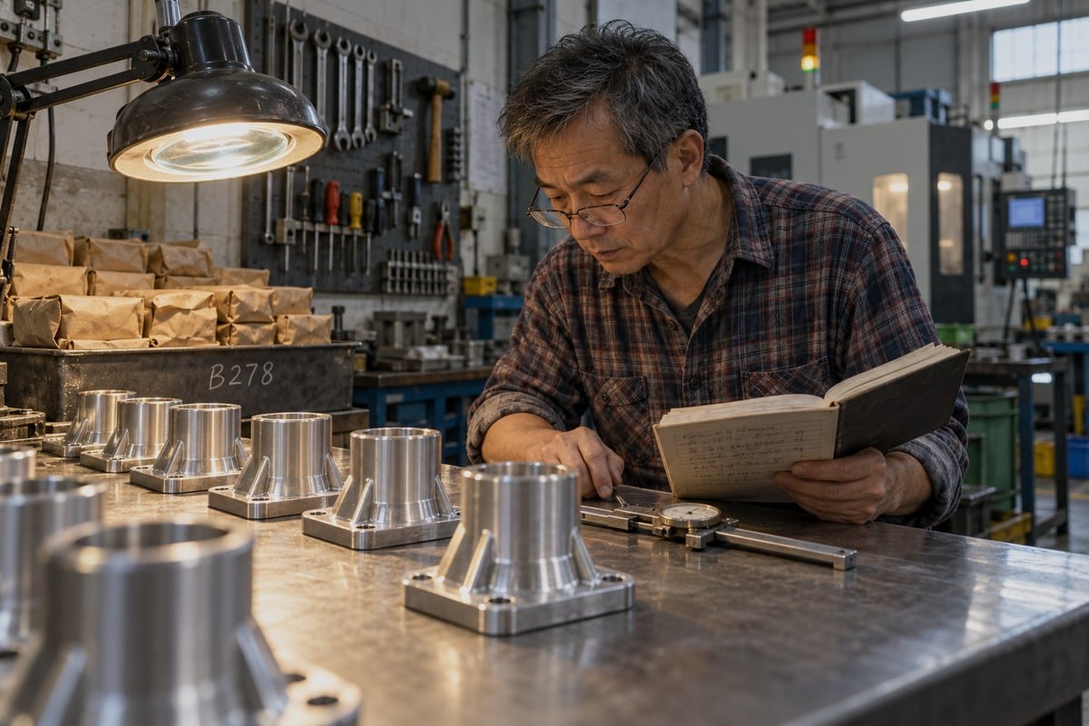
Complex geometry is where aerospace CNC machining earns its keep. But complexity also multiplies the ways a job can go wrong. The process we follow is deliberately slow at the front end so the machine time is clean.
The Workflow From Model to Metal
- Design review and DFM feedback. We flag undercuts, unreachable corners, and walls thinner than the tool can support.
- Stock and datum planning. The datum scheme decides whether features on opposite faces will align.
- CAM programming with CAD/CAM software integration, working from model-based definition where the customer provides it.
- Full simulation to catch collisions and excessive tool engagement before any chip is cut.
- Roughing, stress relief where needed, then semi-finishing.
- Fine finishing on the 5-axis center with in-process probing.
- CMM inspection against the model, then documentation.
Fewer Setups, Better Alignment
The main benefit of five-axis work is not speed. It is that the part never leaves the fixture between faces. Every re-clamp introduces a small positional error. Some industry sources claim five-axis cuts setups by 60% and cycle time by 30%. Those figures are application-specific. On our impeller job the setup reduction was real; the cycle-time saving was smaller because finishing passes dominated. I would treat such numbers as possible outcomes, not guarantees.
Thin Walls and Chatter
Lightweight structural parts often mean 1 mm walls over deep pockets. These ring like a bell under the tool. We handle this with trochoidal roughing, step-down finishing, and sometimes sacrificial support ribs that are removed last. Machine-learning-based chatter suppression, which adjusts spindle speed from vibration data, is emerging on new controls. It is promising, but I still rely on proven fixturing first.
The Monolithic Part Objection
A product development manager once asked why he should merge five brackets into one machined piece if it costs more per part. Fair question. A monolithic part removes fasteners, joints, and assembly labor. But it increases programming time, material waste, and inspection complexity. If it is damaged, the whole piece is replaced. The table below is how we frame it.
| Approach | Best When | Trade-Off |
|---|---|---|
| Monolithic machined part | Alignment is critical, volume is low | Higher unit cost, costly to replace |
| Multiple simple parts | Field replacement matters | More fasteners, stack-up error |
| Additive plus CNC finishing | Internal channels, topology-optimized shapes | Needs qualified AM source, then machining |
Protecting the Program Itself
One more point buyers now ask about. The G-code is the part. A tampered or wrong-revision program produces consistently wrong hardware. We lock revisions, control access to CAM files, and verify the post-processor output through simulation. This also applies to rapid prototyping for aviation, where a fast iteration must still match the released model.
What Quality Certifications Should I Look for in an Aerospace CNC Machining Supplier?
Years ago I learned that a certificate on the wall cannot stop a wrong revision reaching the spindle. Our ISO 9001:2015 4 system only works when paperwork follows every part.
Look for ISO 9001:2015 as the baseline, AS9100 quality standards for aerospace-specific process control, and NADCAP accreditation for special processes like heat treatment or NDT. Also verify first-article inspection reports, CMM data, material certificates, and lot traceability for every shipment.
CNC capability alone does not make a part aerospace-grade. The controlled process around the machine does. That is the honest stance I take with every buyer who asks about our credentials.
What Each Certification Actually Covers
| Certification | Scope | What It Does Not Prove |
|---|---|---|
| ISO 9001:2015 | General quality management system | Aerospace-specific controls or customer approval |
| AS9100 | Aerospace quality standards built on ISO 9001, adds risk, configuration, and counterfeit-part control | Approval for special processes |
| NADCAP | Accreditation for special processes such as heat treatment, NDT, coatings, welding | Machining quality or dimensional capability |
| Customer-specific approval | Program-level audits, process qualification | Transferable to other programs |
Where We Stand and Where We Are Honest
Our factory in Dongguan is ISO 9001:2015 certified, and that system runs every job, from one-off prototypes to mass production. When a buyer needs AS9100-level documentation 5 or NADCAP-accredited special processes such as anodizing or NDT, I say so plainly. We tell the customer which steps happen on our floor and which go to approved partners. A supplier that claims every certification for every process is the one I would question.
Documents to Ask for Before You Order
Certificates are the start. The documents below are what prevent assembly failures.
- First-article inspection report with ballooned drawing
- CMM dimensional report per lot or per serial
- Material certificate traceable to the mill heat number
- Heat-treatment and surface-finish records where applicable
- Revision control confirmation showing which model was cut
- Outgoing inspection record before shipment
Why Paperwork Equals Repeatability
Here is the lesson behind this section. Aerospace assemblies contain thousands of interacting parts, and a small error at one interface stacks up across the whole structure. Traceability is what lets you find where a problem started. On our line, every lot carries its inspection data, and we back the parts with a 30-day warranty. If a bore drifts, we can trace the tool, the batch, and the probe log. That is what buyers in the US and Germany mean when they ask for "German quality at Asia price." They want the paper trail, not just the price.
Conclusion
Aerospace parts fail when tolerance, material, geometry, or paperwork slips. CNC machining supports the aerospace industry only when all four are controlled together, batch after batch.
Footnotes
1. Official site for the Nadcap program, which manages accreditation for aerospace industry special processes. ↩︎
2. Authoritative government source for aerospace research and material standards used in flight hardware. ↩︎
3. Official regulatory body for civil aviation, overseeing standards for aircraft engines and components. ↩︎
4. Official landing page for the ISO 9001 quality management standard mentioned in the quality section. ↩︎
5. Homepage of SAE International, the organization responsible for developing and maintaining the AS9100 aerospace standard. ↩︎

 العربية
 English
 Italiano
 Français
 日本語
 Deutsch (Sie)
 Español
 Русский
 Български
 Čeština
 Dansk
 Suomi
 עִבְרִית
 हिन्दी
 Nederlands
 Português
 Română
 Slovenčina
 Svenska
 ไทย
 Tiếng Việt
 Türkçe
 Slovenščina