

Every week, our engineering team reviews quotes where a small design tweak could save a buyer 30% or more — yet the opportunity slips by because no one flagged it before production started.
You can reduce CNC machining costs by simplifying part geometry, choosing machinable materials like aluminum, relaxing tolerances on non-critical features, leveraging DFM feedback from your supplier, and ordering in larger batches to spread fixed setup costs across more units.
The strategies below come straight from two decades of running CNC mills and lathes in our Dongguan facility. Each section targets a specific lever you can pull — design, material, tolerance, or process — to bring your per-part cost down without sacrificing function.
How can I optimize my part design to lower manufacturing expenses?
A buyer in the automotive sector once sent us a bracket drawing with six deep pockets, sharp 90° internal corners, and thin walls that demanded special fixturing — tripling the quoted price compared to a functionally identical but simpler version we proposed.
Optimizing part design means removing unnecessary features, increasing internal corner radii, limiting pocket depths, and breaking complex shapes into simpler sub-components that reduce setups, tool changes, and overall machining time.
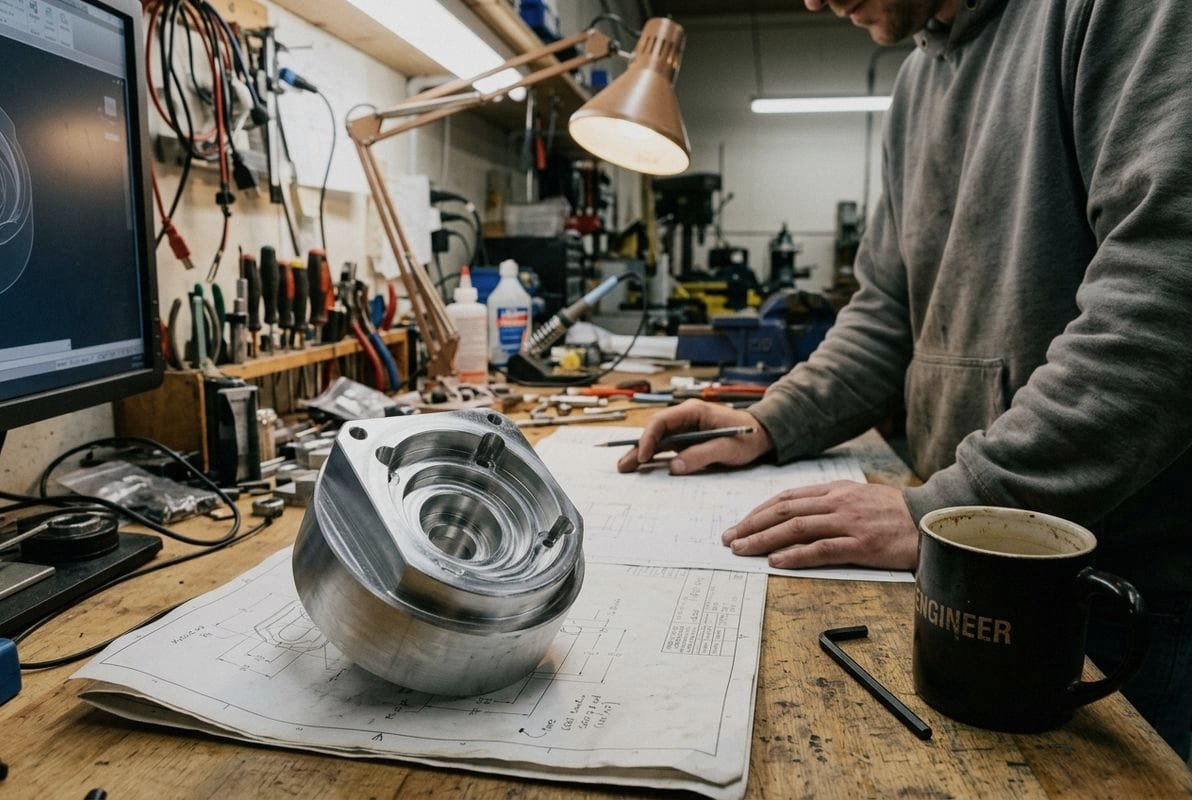
Part geometry simplification 1 is the single biggest lever for cutting CNC costs. When our programmers receive a file, the first thing they evaluate is how many setups the part requires. Every additional setup means re-fixturing, re-zeroing, and more idle machine time. A part that can be machined in two setups instead of four can easily cost 40% less.
Avoid Sharp Internal Corners
A sharp 90° internal corner forces the use of a very small end mill. Small tools cut slowly and break easily. If you increase the internal corner radii 2 to at least one-third of the pocket depth, a larger, more rigid tool can do the job faster.
Keep Pockets Shallow
Deep pocket design drives cost up quickly. When the depth-to-width ratio exceeds 4:1, the cutter must slow down, multiple passes are needed, and tool deflection becomes a quality risk. Aim for a cavity depth no greater than four times its length.
Maintain Adequate Wall Thickness
Thin walls vibrate during cutting, which causes chatter marks and can scrap the part entirely. For metal parts, keep walls at or above 0.794 mm (1/32"). For plastic, stay above 1.5 mm. This wall thickness optimization avoids the need for custom fixtures to dampen vibration.
Break Complex Parts into Sub-Components
Instead of machining a single monolithic block with undercuts on every face, consider splitting the design into two or three pieces that bolt or press-fit together. Each piece becomes simpler to machine, may need fewer setups, and can even use different, less expensive materials where appropriate.
| Design Feature | High-Cost Approach | Low-Cost Alternative | Typical Savings |
|---|---|---|---|
| Internal corners | Sharp 90° corners | Radius ≥ ⅓ pocket depth | 15–25% |
| Pocket depth | Depth > 4× width | Depth ≤ 4× width | 10–20% |
| Wall thickness | < 0.5 mm metal | ≥ 0.794 mm metal | Avoids scrap |
| Part complexity | Single monolithic part | Bolted sub-assemblies | 20–40% |
| Setups required | 4+ setups | 1–2 setups | 30–50% |
A common misconception is that splitting a part into sub-components always adds cost because you're machining more pieces. In practice, the reduction in setup time and tooling complexity often outweighs the extra piece count.
Which materials should I choose to keep my CNC machining budget under control?
One lesson we learned early when exporting to the US market is that many buyers default to 316 stainless steel or titanium on drawings even when the part never sees corrosive fluids or extreme temperatures — and then are surprised by the quote.
Choose materials that balance function with machinability: aluminum 6061 and mild steel 1018 cut fast, cause minimal tool wear, and cost less per kilogram than stainless steel or titanium, making them ideal for non-extreme environments.
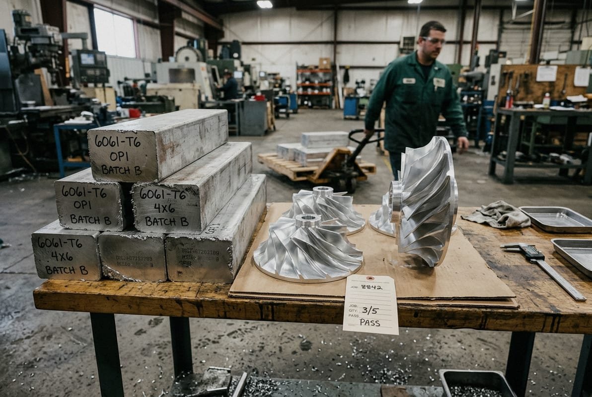
Material selection affects every downstream cost: cutting speed, tool life, cycle time, and even surface finish requirements. A part machined from 6061-T6 aluminum 3 might take 15 minutes on our 5-axis mill. The same geometry in 17-4 PH stainless 4 could take 45 minutes and consume two or three times the tooling.
Machinability Comparison
Not all metals behave the same under a cutter. Free-machining alloys 5 contain additives that help chips break cleanly, reduce heat buildup, and extend tool life. The table below ranks common materials by relative machinability.
| المواد | Relative Machinability | Tool Wear | Typical Use Case | Relative Cost per kg |
|---|---|---|---|---|
| Aluminum 6061-T6 | Excellent | Low | Housings, brackets, heat sinks | Low |
| Brass C360 | Excellent | Very low | Fittings, connectors, bushings | Medium |
| Mild Steel 1018 6 | Good | Moderate | Structural brackets, fixtures | Low |
| Stainless Steel 304 | Fair | High | Food/medical equipment | Medium-High |
| Titanium Grade 5 | Poor | Very high | Aerospace, implants | Very High |
| PEEK | Good | Low | Medical, semiconductor | Very High |
When Expensive Materials Are Justified
I am not suggesting you always pick the cheapest option. Aerospace component buyers need titanium or Inconel for a reason. Medical implants must use biocompatible grades 7. The key is to limit premium materials to the features that truly demand them. A radial impeller spinning at 50,000 RPM justifies aerospace-grade aluminum. The mounting bracket holding it in place does not.
Leverage Standard Stock Sizes
When we quote parts, raw material cost is a line item. If your part dimensions force us to order a non-standard billet, the material price jumps. Design your part roughly 3 mm smaller than a standard blank size, and we can pull stock off the shelf. This also reduces material waste and shortens lead time.
For production volume optimization on large orders, bulk material purchasing can lower the per-unit price substantially. We pass those savings through because the procurement effort is the same whether we buy 10 kg or 200 kg.
Will relaxing my tolerance requirements significantly reduce my total project cost?
During a recent project review, an engineer from a European automation company had specified ±0.01 mm on every dimension of a 24-feature housing. After we walked through the assembly together, only four of those dimensions truly needed that precision. Relaxing the rest to ±0.05 mm cut the machining time almost in half.
Yes — relaxing tolerances on non-critical features can reduce costs by 20–50%, because tighter tolerances demand slower feed rates, more inspection steps, finer tooling, and sometimes additional finishing passes that all multiply cycle time and labor.

Tolerance specifications are one of the most misunderstood cost drivers in CNC machining. Many designers apply a blanket tight tolerance across an entire drawing for safety. The logic seems sound — "better safe than sorry." But in practice, this approach inflates cost dramatically and often delivers no functional benefit.
How Tolerances Affect Machining Time
When our operators see ±0.01 mm on a dimension, they must take a lighter finishing pass, measure with a CMM or precision gauge, and sometimes compensate for thermal expansion. That finishing pass alone can add 30% to cycle time for that feature. Multiply this across every dimension, and you have a very expensive part.
A standard tolerance of ±0.127 mm (±0.005") is achievable with normal CNC processes, no special effort, and no additional inspection burden. This is the sweet spot for non-critical features.
A Practical Tolerance Strategy
- Identify functional interfaces. Which surfaces mate with another part, seal against an O-ring, or locate a bearing? These need tight tolerances.
- Define a single datum. Dimension everything from one reference point. This simplifies both machining and inspection.
- Apply standard tolerances everywhere else. Use ±0.005" (±0.127 mm) as your default.
- Call out only critical features. Mark GD&T callouts only where they are functionally necessary.
| Tolerance Range | Typical Application | Impact on Cost | Inspection Method |
|---|---|---|---|
| ±0.005 mm | Bearing bores, sealing surfaces | Very high | CMM, roundness tester |
| ±0.01 mm | Precision fits, alignment pins | High | CMM |
| ±0.025 mm | Dowel holes, locating slots | Moderate | Digital caliper, CMM |
| ±0.05 mm | General mating surfaces | Low | Digital caliper |
| ±0.127 mm (±0.005") | Non-critical dimensions | Baseline | Standard shop tools |
| ±0.25 mm | Cosmetic edges, clearance holes | Minimal | Visual + caliper |
Some industry voices argue that you should always specify tolerances explicitly — even loose ones — rather than leaving them to the shop's default interpretation. I agree. Specifying a general tolerance like ISO 2768-m 8 on the drawing title block removes ambiguity. The cost reduction comes not from leaving tolerances unspecified but from choosing the right CNC machining tolerances for non-critical features.
The Balance Between Cost and Function
Relaxing tolerances too far can backfire. If a locating pin hole is too loose, the assembly wobbles. If a sealing groove is too wide, the O-ring leaks. The goal is to find the widest tolerance that still delivers the part's intended function. Our DFM review process flags dimensions where tighter control adds cost without adding value, and we share this feedback before production begins.
How can I use DFM feedback from my supplier to eliminate unnecessary machining steps?
A trade-off we weigh on nearly every quote is whether to flag a costly feature to the buyer or simply machine it as drawn. We always choose transparency. One recent example: a US customer's impeller design called for a decorative chamfer on an internal channel no one would ever see. Removing it saved two tool changes and 12 minutes per part.
DFM feedback from your supplier identifies features that are expensive to machine but add no functional value — such as unnecessary chamfers, overly deep threads, or redundant surface finishes — so you can eliminate them before production and cut costs without compromising performance.
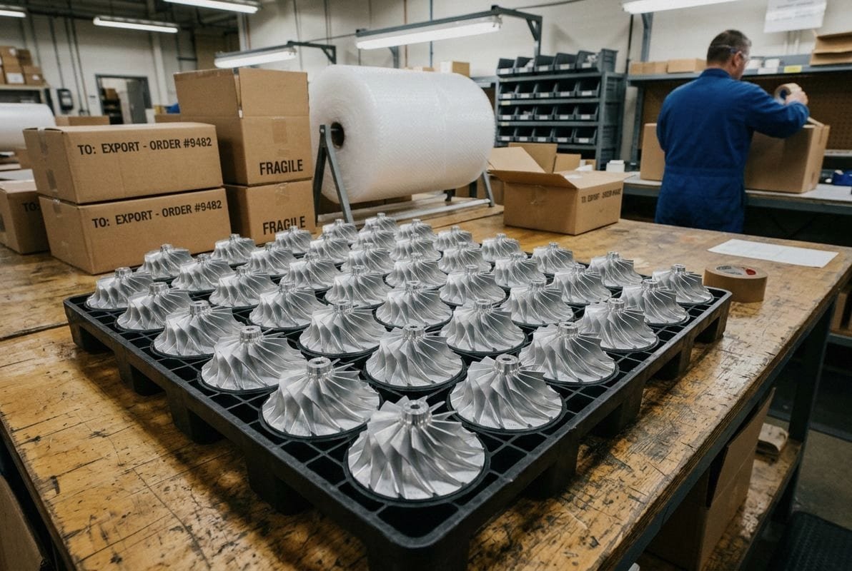
Design for Manufacturability (DFM) 9 is not just a buzzword. It is a structured review process where manufacturing engineers examine your design and suggest changes that reduce cost, improve quality, or shorten lead time. At our facility, every new project goes through a DFM check before we finalize a quote.
What a Good DFM Review Covers
A thorough DFM review goes feature by feature through your 3D model and 2D drawing. Here is what our team typically evaluates:
- Standard tooling compatibility. Can every feature be cut with standard drill sizes, end mills, and taps? Custom tooling adds cost and lead time.
- Number of setups. Can the part be re-oriented to reduce fixturing changes?
- Thread depth and size. Holes threaded deeper than 4× diameter require special taps and slow the process. We recommend keeping thread depth at 3× diameter when possible.
- Surface finish requirements. Specifying a mirror finish (Ra 0.4 µm) on a surface that will be hidden inside an assembly wastes time and money. A standard as-machined finish (Ra 1.6–3.2 µm) is usually sufficient.
- Undercuts and internal features. These may require special tooling or EDM, which adds cost.
How to Act on DFM Feedback
When we send DFM feedback, we include a marked-up drawing and a cost comparison. For example:
"Feature 12 — internal thread M3×0.5, depth 20 mm. Current cost impact: +$2.40/part. Recommended change: reduce depth to 12 mm. Savings: $1.80/part."
This level of detail lets you make informed decisions. Sometimes the deep thread is critical and you keep it. Other times, it is leftover from a copy-paste error on an earlier revision. Either way, the manufacturing process optimization happens before chips start flying, not after.
Why Early Collaboration Matters
The earlier you involve your machining supplier, the more options you have. Once a design is frozen, tooling is ordered, and fixtures are built, changes become expensive. We encourage buyers to share preliminary drawings — even rough 3D models — so we can flag issues before the design is finalized. This approach aligns with a growing trend in digital collaboration where buyers and suppliers iterate on models in real time.
Specifying only the final characteristics on your drawing — dimensions, tolerances, surface finish — rather than prescribing the process (e.g., "mill with a 6 mm end mill") gives the manufacturing team flexibility. We may find a faster or cheaper path to the same result using a different cutter, a different machining sequence, or a combination of turning and milling on our multi-axis machines.
Machining Time Reduction Through Process Flexibility
When a drawing says "surface grind this face to Ra 0.8," the shop must set up a grinding operation. But if the drawing says "Ra 0.8 on this face" without specifying the process, we might achieve it with a fine finishing pass on the mill — eliminating an entire secondary operation. Machining time reduction often comes from this kind of process flexibility.
Conclusion
Reducing CNC machining costs comes down to smarter design, appropriate materials, sensible tolerances, and early supplier collaboration — not cutting corners on quality. Start your next project with a DFM review, and the savings will follow.
Footnotes
1. Explains the importance of simplifying part geometry in manufacturing to reduce costs. ↩︎
2. Details how increasing internal corner radii improves machining efficiency and reduces tool wear. ↩︎
3. Provides information on the properties, applications, and benefits of 6061-T6 aluminum alloy. ↩︎
4. Provides information on the properties, applications, and machinability of 17-4 PH stainless steel. ↩︎
5. Explains the composition and benefits of free-machining alloys in improving machining processes. ↩︎
6. Offers details about the characteristics, composition, and uses of Mild Steel 1018. ↩︎
7. Defines biocompatible materials and their critical importance in medical implant applications. ↩︎
8. Replaced HTTP 403 with a relevant and authoritative guide on ISO 2768-m in CNC machining from Fictiv. ↩︎
9. Explains the principles and benefits of Design for Manufacturability in product development. ↩︎

 العربية
  English
  Italiano
  Français
  日本語
日本語  Deutsch (Sie)
  Español
  Русский
  Български
  Čeština
  Dansk
Dansk  Suomi
Suomi  עִבְרִית
  हिन्दी
  Nederlands
  Português
  Română
  Slovenčina
  Svenska
  ไทย
ไทย  Tiếng Việt
  Türkçe
  Slovenščina