
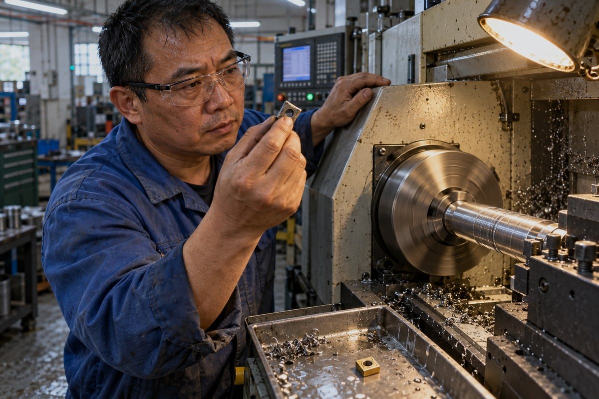
Tool wear erodes CNC machining quality on our Dongguan production line, and nothing in the program changes. Parts drift, finishes roughen, and batches fail inspection unless we catch it early.
Tool wear degrades CNC machining quality by changing the cutting edge geometry while the program stays the same. Flank wear, crater wear, and built-up edge cause dimensional drift, visible tool marks, angular deviation, burrs, higher cutting forces, and vibration, so parts fall outside machining tolerances before the tool breaks.
The CNC code does not know the tool has changed. It sends the same coordinates on part one and part five hundred. The edge, however, is no longer the same shape. Below, I explain how to spot the problem, what it does to your parts, how to judge a supplier, and how to keep wear from spoiling a batch.
How Can I Tell If Tool Wear Is Affecting My Machined Parts?
Last year our inspector pulled a turned stainless housing from the line. The diameter was still in tolerance, but the feed marks had clearly deepened since the first article.
You can tell tool wear is affecting machined parts when surface roughness rises, tool marks become visible, dimensions drift in one direction, burrs appear at edges, angles deviate from the drawing, spindle load climbs, or cutting noise changes. These signs usually appear before the tool visibly fails.

That housing taught our team something simple. The part can pass a micrometer check and still be a warning. In our experience, the finish goes first, then the angles, then the size. The author's own shop records point the same way: a worn edge produces obvious tool marks and angular deviation, and both of those feed straight into lost dimensional accuracy.
Signs you can see on the part
Here is the checklist we use at the inspection bench. It splits symptoms by the wear type most likely behind them.
| Symptom on the part | Most likely wear type | What we check next |
|---|---|---|
| Deeper, more regular feed marks | Flank wear 1 | Flank-wear land under magnification |
| Random scratches or small gouges | Edge chipping | Edge under 20x loupe, look for missing micro-fragments |
| Torn, smeared, or dull surface patches | Built-up edge 2 | Chip morphology, cutting speed, coolant delivery |
| Chamfer or taper angle off the drawing | Nose-radius wear or uneven insert wear | Profile on the CMM against the first article |
| Diameter drifting in one direction | Flank wear or radial wear | Trend of the last 10 to 20 parts, not a single reading |
| Burrs at hole exits and slot edges | Rounded edge, rubbing instead of shearing | Deburring time per part, which is a hidden cost signal |
The direction of drift matters. Gradual flank wear moves a dimension steadily one way. Chipping scatters it. So if your diameters creep up by a few microns per part, you are watching wear. If they jump around, you are watching damage.
Signs you can hear and measure on the machine
The machine often tells us before the part does. Spindle load climbs as the rounded edge ploughs instead of cuts. The cutting sound changes pitch. Chip morphology shifts too; chips get thicker, bluer, or more ragged. A less obvious sign is a change in the vibration signature. As the tool loses mass to wear, the resonance frequency of the tool-holder assembly shifts slightly, and a stable cut can start to chatter at the same speed that was fine an hour earlier.
Two more signals catch many buyers by surprise. First, a worn tool used for automated datum setting can introduce probing errors, because the effective edge position no longer matches what the control assumes. Second, worn tools change the light reflection pattern on the surface, so downstream vision inspection systems may flag or miss parts for reasons that look unrelated to the cutter.
Why the finish fails before the size
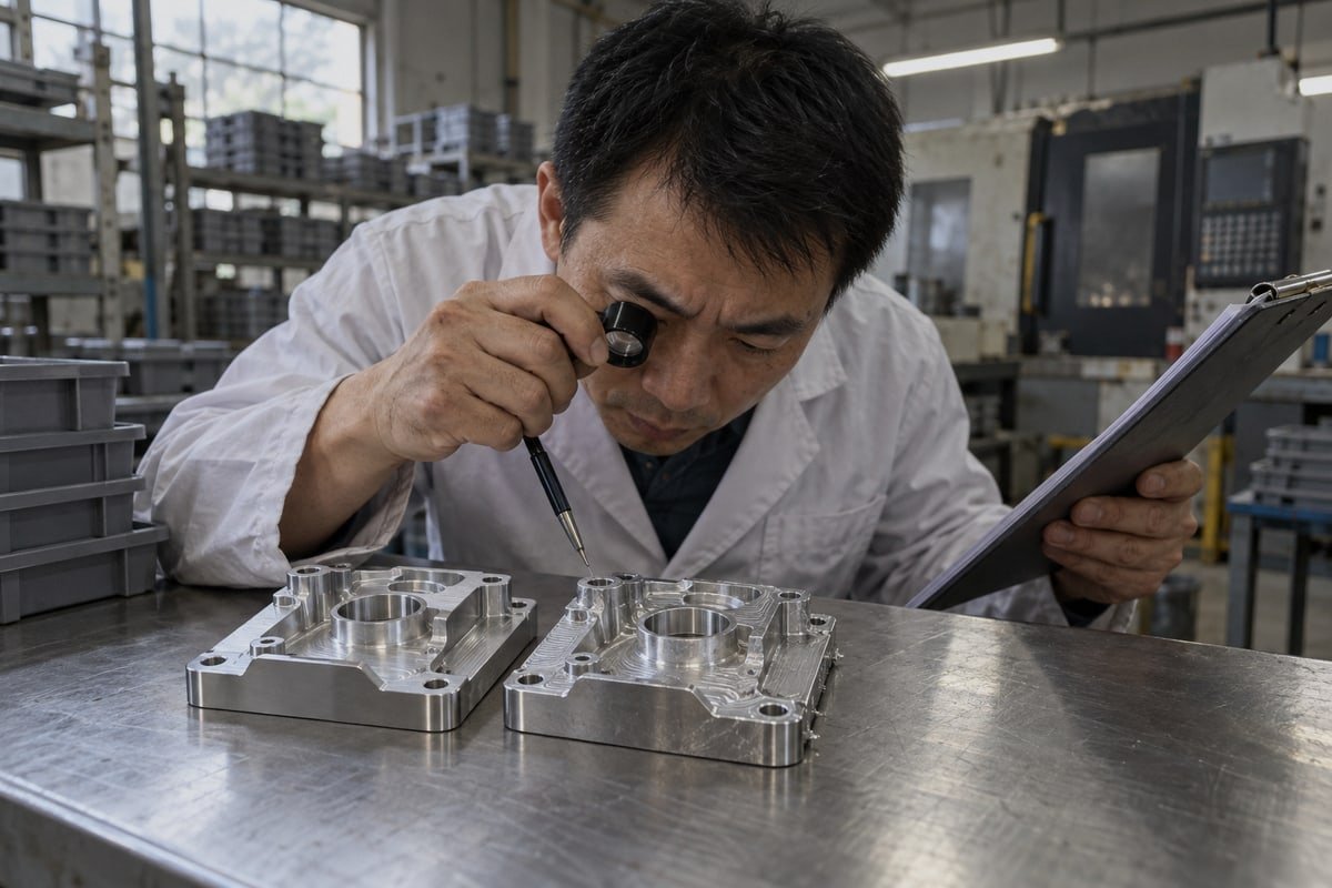
A finishing tolerance of 0.01 mm leaves little room, but a surface roughness limit often has even less. The rounded edge rubs and generates heat long before it removes enough extra material to push a diameter out. That is why our inspectors photograph surface finish on the first article and compare it against later samples, rather than relying only on gauge readings.
What Quality Problems Does Tool Wear Cause in CNC Machining?
Every time we quote a batch with a ±0.01 mm feature, we weigh tool cost against scrap risk. That decision depends on how far wear moves the edge.
Tool wear causes dimensional drift beyond machining tolerances, rougher surface finish with deeper tool marks, angular and profile deviation, burrs at edges, higher cutting forces and heat, thermal deformation, chatter marks, and sudden quality cliffs after coating delamination. Together these lead to assembly failures and rejected batches.
The core point is this: a tool keeps cutting long after it stops producing acceptable parts. When we machine the aluminum mold bases or cylindrical housings shown on our product pages, the same end mill runs through hundreds of pockets and bores. Its geometry at the end of the run is not the geometry we programmed for.
Each wear type damages quality differently
| Wear type | Where it forms | Mechanism | Main quality effect |
|---|---|---|---|
| Flank wear | Clearance face | Rubbing against the machined surface | Gradual dimensional drift, higher friction, poorer finish |
| Crater wear | Rake face | Hot chips flowing over the tool | Unstable chips, edge weakening, sudden fracture |
| Nose-radius wear | Tool tip in turning | Abrasion at the nose | Profile and angle error, visible feed marks |
| Built-up edge | On the cutting edge | Workpiece material welds to the edge | Torn surfaces, random size errors, burrs |
| Chipping | Edge micro-fractures | Impact, interrupted cuts, fatigue | Isolated gouges, scratches, intermittent defects |
A 2024 study linked built-up edge directly to undesirable marks on machined surfaces, and it found that light finishing passes often cannot remove them. We have seen the same thing in ductile aluminum when the speed was too low or the coolant missed the cutting zone.
The chain reaction from edge to part
I describe it to buyers as a loop. Edge degradation causes more rubbing. Rubbing raises cutting forces 3. Higher forces generate more heat and deflect the tool. Deflection and heat invite vibration. Vibration leaves chatter marks and chips the edge further. Then the loop speeds up.
Heat deserves its own mention. Friction from a worn edge causes thermal deformation 4 of both the tool and the workpiece. A long aluminum part can grow measurably during a cut and then shrink after cooling, so a bore that measured right on the machine can be undersized at the inspection bench. Extra force also matters in difficult materials; in hardened steels or nickel alloys, a worn tool can leave a work-hardened subsurface layer that complicates later operations. We do not claim every worn tool does this. It depends on the material, the tool, the coolant, and how severe the wear has become.
Dimensional accuracy versus repeatability
These two are not the same thing. A worn tool can still be repeatable, producing parts that match each other but all sit outside the drawing. Chipping does the opposite: it ruins repeatability with random errors. One supplier source reports worn tools pushing critical dimensions beyond a ±0.05 mm range in some applications, and an industry estimate suggests surface roughness can rise by roughly 25% to 40% on materials harder than HB 250 as tool degradation progresses. I treat both figures as application-dependent, not universal. Your tool diameter, material, machine rigidity, and tolerance all change the outcome.
The quality cliff
Not all wear is gradual. Coated carbide often behaves well right up until the coating delaminates. Then wear accelerates sharply, and rejection rates jump within a few parts. This non-linear cliff is why we never rely on a fixed part count alone to decide when a tool is done.
How Do I Choose a Supplier That Monitors Tool Wear Effectively?
A German procurement manager once asked me a simple question: how do you know when to change an insert? He wanted a measured answer, not a feeling.
Choose a supplier that sets tool replacement limits on measured flank wear and part data, not on maximum tool life. Look for in-process probing, spindle load monitoring, documented tool-life tracking per material and operation, ISO 9001:2015 certification, first article inspection, and inspection reports across the full batch.

My answer to that manager was a trend chart, not a shrug. Our team at the Chang'an factory tracks each tool by material, operation, and tool position, and the replacement point comes from the part data. That is what you want to hear from any supplier. The Taylor relationship 5, V·Tⁿ = C, gives a useful idea of how cutting speed shortens tool life, but it says nothing about your tolerance or your finish spec. Real replacement decisions need more inputs.
Questions worth asking before you place an order
| Question to ask | Answer that builds confidence | Red flag |
|---|---|---|
| How do you decide when to replace a tool? | Measured flank-wear land, drift trend, roughness check, spindle load | "When it breaks" or "when it looks bad" |
| Do you probe parts during the run? | Yes, at defined intervals, with offsets updated from results | Only the first and last part are measured |
| Do you track tool life by material? | Separate records for aluminum, stainless, titanium, PEEK | One generic part-count rule for everything |
| Can I see batch inspection data? | Dimensional reports across the run, first article report, material cert | A single sample report for the whole lot |
| What happens if parts drift mid-batch? | Documented stop, inspect, compensate or replace decision | No defined response |
Manual, machine-based, and data-driven monitoring
A good supplier combines three layers. Manual methods include inspecting inserts under magnification, measuring the flank-wear land optically, and checking parts with micrometers, gauges, or a CMM. Machine-based methods watch spindle motor current, cutting force, vibration, acoustic emission, and power consumption. Data-driven systems add sensor fusion and machine learning to predict remaining useful life.
I am honest with buyers about the limits. A spindle-load spike may come from workpiece hardness variation, a coolant problem, or loose fixturing, not only from wear. Models trained on one tool and material rarely transfer cleanly to another. False alarms stop machines for nothing. Recent research describes radial wear as a relatively stable criterion for predicting machining quality, and that aligns with what we see: a measured, physical wear indicator beats a clever model with poor data.
Resolving the objection: does monitoring cost more?
Buyers sometimes worry that a supplier with monitoring and probing will quote higher. In practice, the cost shifts rather than grows. The alternative, running a tool until measurable failure, gives the lowest tool cost per part but the highest scrap risk, the heaviest inspection burden, and the hardest root-cause analysis when something goes wrong. A supplier that replaces tools on a quality threshold spends a little more on inserts and saves far more on rework, returns, and schedule slips. Our 30-day warranty and pre-shipment inspection only make commercial sense because we control wear before it reaches the box.
What Steps Can I Take to Prevent Tool Wear from Ruining My Batch Production?
The hardest lesson from twenty years of machining is this: an offset adjustment hides a size problem but never repairs a worn edge. A steel turning batch taught us.
Prevent tool wear from ruining batch production by matching tool material and coating to the workpiece, validating cutting parameters on the first article, controlling coolant delivery and runout, probing parts at set intervals, applying wear offsets only for gradual drift, and replacing tools at a quality threshold, not at failure.
Here is the steel turning story. Early parts met both the diameter and the roughness spec. As flank and nose wear developed, cutting forces rose, the tool ran hotter, and the diameter crept. Our operator compensated the offset, and the size came back. The feed marks did not. Burrs appeared at one edge. The inspection data finally showed that a new insert cost less than the extra deburring and sorting. Compensation had masked one symptom and left the other unresolved.
A practical sequence for protecting a batch
- Match the tool to the material. Coatings such as TiN and Al₂O₃, plus carbide or ceramic substrates, are identified in a 2026 review as effective ways to reduce wear and improve surface quality. Hardened steel, titanium, and abrasive composites each need a different choice.
- Start from the manufacturer's parameters, then validate on the first article. Record speed, feed, depth, and radial engagement against measured roughness and size. This becomes the baseline for the run.
- Fix the setup before blaming the tool. Reduce overhang, clean the holder, check runout, and tighten workholding. A flexible setup wears a tool faster than any speed setting.
- Choose a cooling strategy for the job, not by habit. Flood coolant, high-pressure coolant, minimum-quantity lubrication, and dry machining each suit different operations. High pressure helps chip evacuation in deep pockets; interrupted flood on a hot insert can cause thermal shock.
- Probe at defined intervals and plot the trend. Update wear offsets only when the drift is gradual and predictable. Research on CNC turning shows that measuring actual nose-radius wear and compensating the error improves both accuracy and efficiency.
- Set the replacement limit from quality data. Define maximum flank-wear land, allowable drift, and roughness ceiling before the batch starts.
Choosing a replacement strategy
| Strategy | Advantages | Disadvantages |
|---|---|---|
| Replace early on a fixed count | Stable size and finish, low scrap risk, simple scheduling | Higher tooling cost, more waste, more changeover downtime |
| Run until measurable failure | Maximum tool use, lowest tool cost per part | High scrap risk, unpredictable finish, risk of machine damage |
| Replace at a quality threshold | Balances tool cost against scrap, predictable results | Needs measurement discipline and tracked data |
Buyers often ask which one we recommend. The third. Blanket early replacement wastes money on a prototype run of five pieces. Running to failure is reckless on a mass production lot with ±0.01 mm bores. A quality-based threshold adapts to both.
A caution on slowing down
Dropping speed and feed is not a free fix. Lower speed cools the cut and slows diffusion wear, but very low feed causes rubbing and promotes built-up edge in aluminum and other ductile materials. Cycle time rises and cost per part follows. Parameter optimization has to look at the whole process, including tool life, chip control, and your delivery date. When we provide DFM feedback on a drawing, a lot of it comes down to this balance.
Conclusion
Tool wear silently drifts parts out of tolerance. Ignore it and batches fail. Measure it, set quality-based limits, and choose a supplier that does the same.
Footnotes
1. Authoritative engineering database explaining the primary mechanism of tool degradation in CNC machining. ↩︎
2. Detailed explanation of the welding of workpiece material to the tool edge and its effects. ↩︎
3. Scientific overview of how tool geometry changes affect the mechanical forces during metal cutting. ↩︎
4. Current NIST hub for machining metrology and standards, replacing the broken Intelligent Systems Division link. ↩︎
5. Standard mathematical model used in manufacturing to predict the lifespan of cutting tools. ↩︎

 日本語
 English
 Italiano
 Français
 Deutsch (Sie)
 Español
 Русский
 العربية
 Български
 Čeština
 Dansk
 Suomi
 עִבְרִית
 हिन्दी
 Nederlands
 Português
 Română
 Slovenčina
 Svenska
 ไทย
 Tiếng Việt
 Türkçe
 Slovenščina