
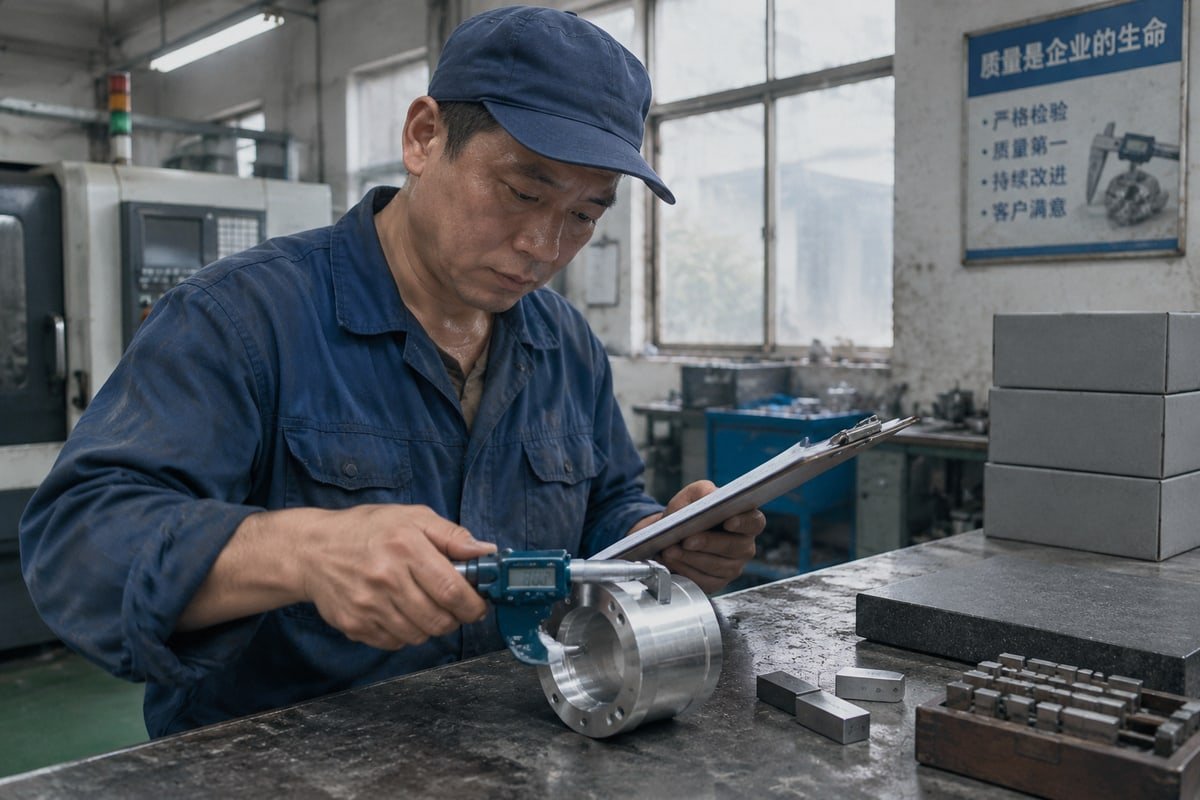
Tight tolerances in CNC machining look simple on a drawing. Then the first batch arrives out of spec. On our production line in Dongguan, we solve that problem daily.
You achieve tight tolerances in CNC machining by specifying only functionally necessary tolerances, choosing a process capable of repeating them, using a rigid calibrated machine, controlling thermal expansion and material stability, reducing tool deflection, separating roughing from finishing, and verifying every critical dimension with calibrated inspection equipment.
That answer is short. The work behind it is not. Below, I walk through the four questions our customers ask most often. Each one builds on the last.
How do I know which tolerance level my CNC part really needs?
Last year a German customer sent us a housing drawing with ±0.01 mm on every dimension. Our DFM review found that only a handful of features actually needed it.
Your CNC part needs the tolerance level that protects function. Identify mating, locating, sealing, and load-bearing features and tolerance those tightly. Leave non-critical profiles at standard tolerances. Ask what happens if a dimension hits either limit; if nothing changes functionally, the tolerance is tighter than necessary.

What a tolerance actually describes
A tolerance is the allowed variation around a nominal size. On a drawing it is one number. In the shop it is several things. Dimensional accuracy is how close a feature lands to its target. Repeatability is whether the next part lands in the same place. Geometric tolerances cover flatness, perpendicularity, position, concentricity, and runout. Surface finish requirements describe texture, not size. A bore can be perfectly sized and still fail because its roundness or finish is wrong.
Many shops treat ±0.001 inch, roughly ±0.025 mm, as the entry point for "tight." I use that number as a reference, not a rule. The real threshold depends on the feature, the material, and the process.
Where tight tolerances belong
Consider the cylindrical optical housings 1 we machine for inspection equipment customers. The lens bore and the bracket locating faces control image alignment. They need close control. The flared base plate and the outer skin do not. If you tighten the base plate anyway, you add machining time, inspection time, and scrap risk. You add no function.
| Feature type | Typical need | Why it matters |
|---|---|---|
| Bearing bore, lens bore, dowel hole | Tight (±0.010 mm or better) | Controls fit and alignment |
| Sealing face, mating flange | Tight on flatness and finish | Prevents leaks and gaps |
| Thread, clearance hole | Standard | Function tolerates variation |
| External cosmetic profile | Standard or loose | No mating relationship |
Use GD&T standards and clear datums
Plus/minus numbers alone cannot describe how features relate. GD&T standards such as ASME Y14.5 2 let you tie position to a datum reference frame. That tells us which face to locate from and which bore to measure to. It also tells our inspector how to align the part on the machine. Without datums, a good part can look bad on a report.
Thermal expansion belongs in this decision too. Aluminum grows more than steel for the same temperature rise. Ask whether your tolerance applies at 20 °C, after assembly, or at operating temperature. Then write that on the drawing.
A common buyer objection is "tighter is safer, so I will tighten everything." I understand the instinct. But moving a feature from ±0.025 mm to ±0.005 mm often changes the process from milling to grinding. That can double the cost of that feature. Spend precision where it earns its keep.
What CNC machining methods help me achieve tighter tolerances?
Every week we weigh the same trade-off: finish a bore on the mill in one setup, or send it to grinding and accept extra lead time and a datum transfer.
Tighter tolerances come from matching the method to the feature: CNC milling and turning for stable features around ±0.010–0.025 mm, grinding, honing, lapping, or wire EDM for features near ±0.005 mm, plus rigid workholding, low-runout toolholders, separate roughing and finishing tools, and in-process probing with closed-loop offset correction.
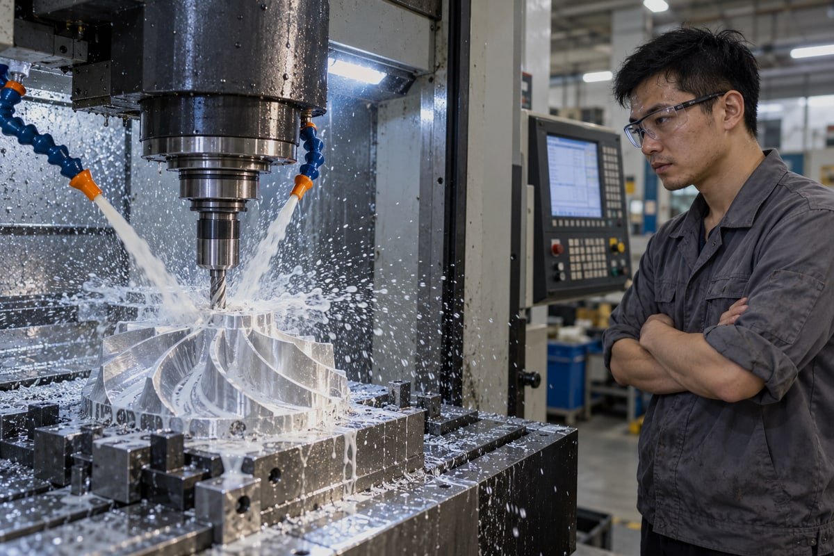
The right method depends on the feature. Here is how I compare the main options before quoting.
| Process | Best for | Practical tolerance range | Trade-off |
|---|---|---|---|
| CNC milling (3/4/5-axis) | Pockets, holes, contours, prismatic parts | ±0.010–0.025 mm without finishing | Tool deflection on deep features |
| CNC turning | Shafts, diameters, tapers, concentric features | ±0.010–0.025 mm | Chuck pressure can distort thin walls |
| Grinding | Very tight size, roundness, finish | Near ±0.005 mm | Extra setup and datum transfer |
| Honing | Precision bores and bore geometry | Near ±0.005 mm | Only for internal cylinders |
| Wire EDM | Hard materials, intricate internal shapes | Fine profiles in hardened steel | Slower, recast layer to manage |
Start with a rigid, calibrated machine
A heavy base, preloaded ball screws, and low spindle runout are the foundation. But I tell buyers that machine specs alone prove nothing. Machine tool calibration must be scheduled and documented. Laser calibration, ball-bar tests, and spindle checks reveal backlash, squareness errors, and circular interpolation errors. Some advanced shops add volumetric error compensation 3 to map and digitally correct 3D deviations across the whole working envelope. A buyer objection I hear often is "just buy a more accurate machine." A better machine cannot fix a loose fixture, a worn tool, or a warm part.
Control tool deflection and runout
Short tool overhang is the cheapest accuracy upgrade there is. Shrink-fit or hydraulic chucks give lower runout than standard collets. Balanced holders matter at high spindle speeds, because imbalance creates vibration. Some shops now use active damping holders that sense and cancel chatter in real time. Another objection: "premium tooling guarantees tighter parts." It does not. A lower-cost tool with correct geometry, stable parameters, and disciplined replacement often beats an expensive tool used badly.
Treat workholding and fixturing as a precision subsystem
The fan-blade style workpieces we run on our 5-axis machines are a good example. Thin ridges flex under cutting load. We support them with custom fixtures and soft jaws cut to the part. Clamping force must be enough to hold, but not enough to distort. A part that is correct while clamped and springs back after release was never correct.
Separate roughing from finishing and tune speeds and feeds
We rough with controlled stock remaining, let the part stabilize, then finish with a dedicated tool. Speeds and feeds optimization is about stable force and predictable heat. Buyers sometimes ask us to "just slow it down." Slower is not always more accurate. Very light cuts can rub instead of cutting, which generates heat and accelerates wear. For heat-sensitive alloys, cryogenic CO2 or liquid nitrogen cooling can hold the cutting zone near a flat thermal gradient.
Probe in process, but still inspect
Spindle probes set datums, verify stock after roughing, and feed offsets back to the control before the final pass. This closed loop catches drift early. Probing is not infallible, though. Stylus calibration, chips, and coolant all affect results. We treat probing as a complement to final inspection, never a replacement.
On our milling line we hold 0.01–0.005 mm on suitable features. When a feature needs more, we route it to wire EDM or a finishing process rather than promise what milling alone cannot repeat.
How do I avoid dimensional drift when scaling up to batch production?
During one mold base run, the first article passed inspection. Partway through the batch, however, our in-process checks showed the bore diameters creeping toward the upper limit.
Avoid dimensional drift in batch production by running repeatable warm-up cycles, holding shop temperature stable, tracking tool wear with tool setters, replacing tools on a fixed schedule, probing parts mid-cycle, charting critical dimensions with Cp and Cpk, and correcting trends before any part leaves tolerance.
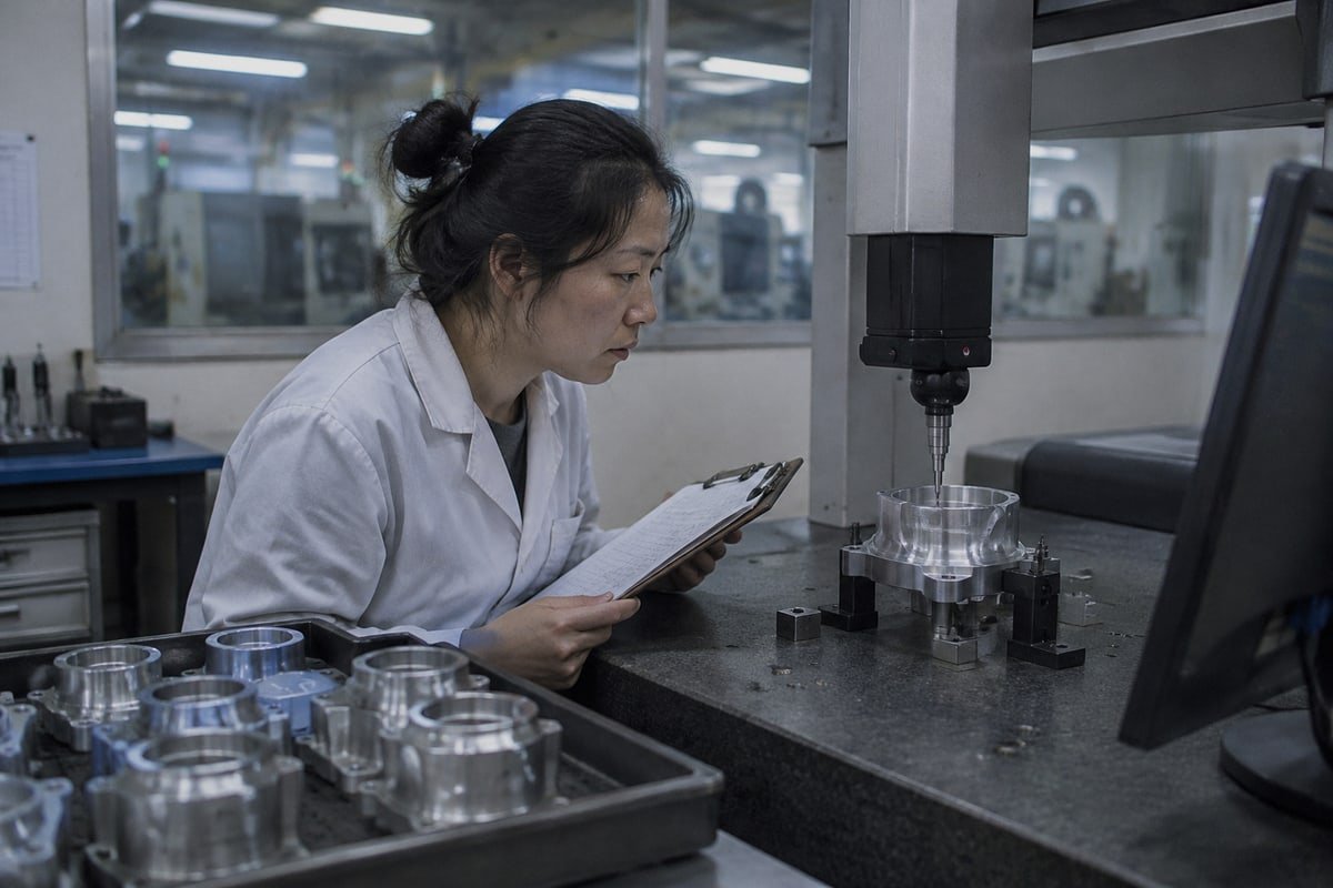
Why the first article passes but the batch drifts
A first article is one part made under one set of conditions. The machine was warm or cold. The tool was new. The shop was at one temperature. Batch production changes all three. Heat from the spindle, ball screws, and cutting friction grows the machine. The workpiece grows too. Tool wear slowly changes effective diameter. Material lots vary in hardness and residual stress. None of these show up in a single sample.
A day-to-night swing of more than 10 °C in the workshop can make consistent tight tolerances almost impossible. We treat temperature as part of the process specification, not as a comfort issue.
A five-step routine we follow
- Run a repeatable warm-up cycle that exercises all axes and the spindle at working speed before any finishing pass.
- Keep coolant temperature and flow consistent, and schedule precision work away from door openings and HVAC cycles.
- Measure tool length and diameter on a tool setter at fixed intervals, and replace finishing tools on a schedule, not when parts fail.
- Probe critical features mid-cycle so the control can update offsets automatically.
- Chart each critical dimension and act on the trend, not on the first reject.
Material stability before the material reaches the machine
Material stability is decided before the first chip. We prefer 7075-T6 aluminum 4 and pre-hardened, stress-relieved alloy steels for parts with tight requirements. For large, thin, or asymmetric parts, we rough, stress relieve, and then finish in a separate operation. Stainless steels work-harden and generate heat. Plastics like POM or PEEK creep under clamping and move with temperature. We specify the material condition on the traveler so it is controlled, not assumed.
| Drift source | What you see on the chart | Control we apply |
|---|---|---|
| Thermal growth | Shift after startup, then settles | Warm-up cycle, climate control |
| Tool wear | Slow steady trend in one direction | Tool setter checks, scheduled replacement |
| Residual stress | Random scatter, part-to-part | Stress relief between roughing and finishing |
| Fixture wear or chips | Sudden jumps between loads | Clean seats, re-probe after loading |
Read the chart, not just the part
Process capability tells you more than a single inspection. A process can be centered but highly variable, or repeatable but offset from nominal. Cp captures the spread. Cpk captures the spread and the centering together. The two problems need different fixes. An offset needs a work offset correction. Variability needs a root-cause investigation into tooling, fixturing, or temperature.
One buyer objection deserves a fair answer: "full climate control is too expensive for my parts." I agree it can be. Environmental control should scale with the tolerance. A ±0.1 mm bracket does not need an inspection room at 20 °C. A ±0.005 mm bore does.
How do I choose a CNC machining supplier that can consistently hold tight tolerances?
Twenty years of machining for European and North American buyers has shown us one truth: tolerance claims on a website mean little until rework is needed.
Choose a supplier with proven experience on similar high-precision parts, a quality system that matches the product, such as ISO 9001:2015, calibrated CMM inspection, documented first-article and batch reports, honest capability statements, DFM feedback, and a demonstrated ability to handle rework rather than hide it.
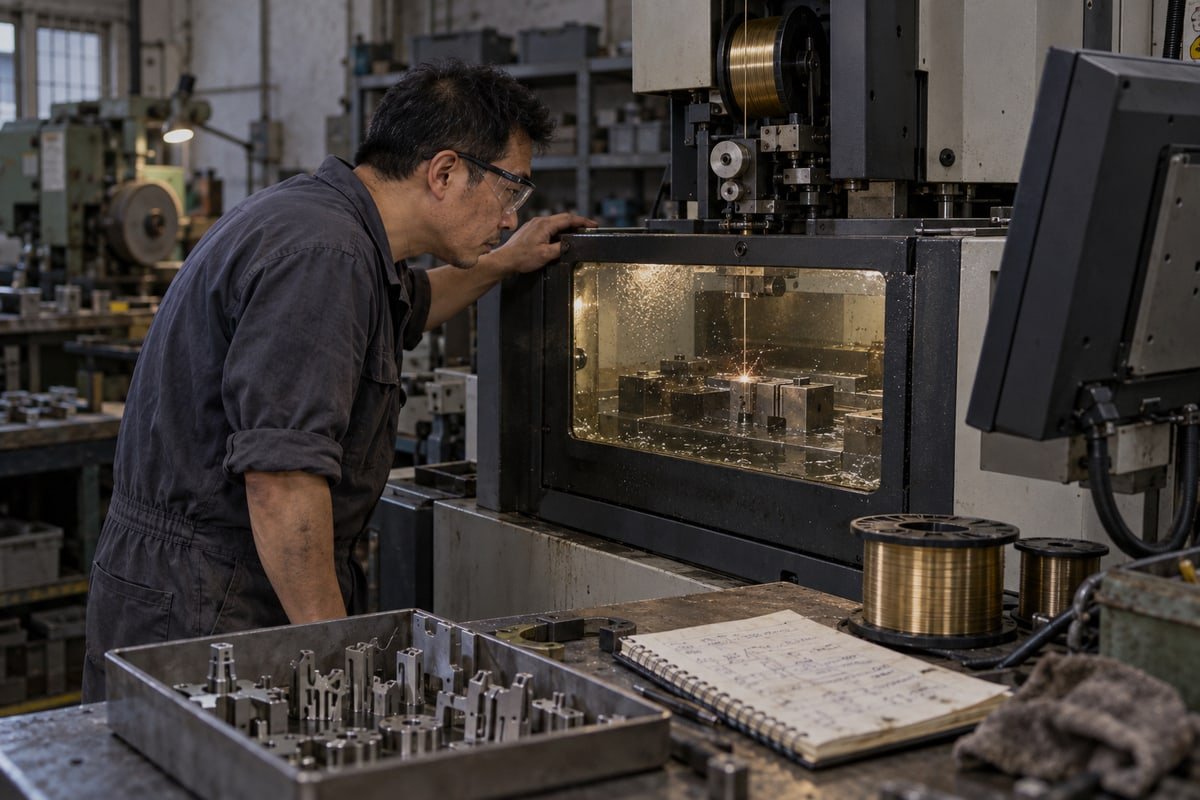
Experience on similar parts matters more than machine lists
Here is the lesson that shapes how we run our own factory. High-precision designs need technicians who have already machined similar products many times. A programmer who has fought thin-wall springback on optical housings knows where to leave stock and how to clamp. A programmer seeing it for the first time will learn on your parts. The quality control process also has to match the product. A tight-tolerance medical component needs a different inspection flow than a bracket.
Factories that rarely take on difficult designs face a second problem. When something goes wrong, they often cannot handle the rework. They lack the fixtures, the measurement data, and the judgment to recover a part safely. So the project stalls. Ask a supplier directly: "When a critical bore came in undersize, what did you do?" The answer tells you a great deal.
Does the inspection system prove the tolerance?
Inspection must be more accurate than the tolerance it checks. The common guideline is ten to one. A ±0.01 mm feature needs a method good to about 0.001 mm. That means a Coordinate Measuring Machine 5 in a temperature-stabilized room, air gauges for repeatable bores, and calibrated micrometers and gauge pins, not a caliper on the shop floor. Ask whether parts are measured at a consistent temperature. A hot part measured straight off the machine will shrink later.
Another buyer objection is "the report shows four decimal places, so it must be accurate." More decimals are not more accuracy. Resolution and calibration are separate things. Ask for the gauge R&R approach, not the decimal count.
Questions to ask before you award the order
| Question | Good answer | Warning sign |
|---|---|---|
| Have you made parts like this before? | Shows similar features, materials, and tolerances | Only shows a generic machine list |
| How do you verify ±0.005 mm features? | CMM or air gauge, controlled temperature, calibrated | Caliper or "experienced operator" |
| What tolerance can you repeat in batch? | States milling range, then names grinding or EDM for tighter | Promises one number for everything |
| What documents ship with the parts? | First article report, dimensional report, material certificate | "We can provide if needed" |
| How is machine tool calibration handled? | Scheduled laser or ball-bar checks with records | No schedule, no records |
| What happens if parts fail at my site? | Clear rework or remake process and warranty | Vague or no commitment |
What honest capability looks like
Some suppliers report around ±0.005 mm in common materials under optimized conditions, and around ±0.0025 mm in especially controlled circumstances. I present these as benchmarks, not guarantees, and I expect any supplier to do the same. Our own milling capability is 0.01–0.005 mm on suitable features. Beyond that, we say so and route the feature to wire EDM or finishing.
Look for DFM feedback before the quote, not after the failure. Look for an ISO 9001:2015 6 system that is actually used. Look for a warranty, such as the 30-day coverage we attach to shipments, that puts the supplier's money behind the tolerance. That is how tight tolerances in CNC machining survive the trip from drawing to assembly line.
Conclusion
Loose process control turns tight tolerances into scrap and delays. Define function first, match the process, control heat and material, verify with calibrated inspection, and partner with experienced technicians.
Footnotes
1. Context for the specific precision components mentioned. ↩︎
2. Official site for the GD&T standard mentioned in the article. ↩︎
3. Authoritative NIST publication detailing measurement, modeling, and compensation strategies for machine tool volumetric errors. ↩︎
4. Technical data on the aluminum alloy used in precision machining. ↩︎
5. Authoritative definition of the inspection equipment. ↩︎
6. Official ISO page for the quality management standard. ↩︎

 ไทย
 English
 Italiano
 Français
 日本語
 Deutsch (Sie)
 Español
 Русский
 العربية
 Български
 Čeština
 Dansk
 Suomi
 עִבְרִית
 हिन्दी
 Nederlands
 Português
 Română
 Slovenčina
 Svenska
 Tiếng Việt
 Türkçe
 Slovenščina