

Choosing the best tolerances for precision CNC parts 1 trips up many drawings that reach our Dongguan shop. Over-tight numbers inflate quotes. Loose numbers break assemblies. There is a smarter path.
The best tolerances for precision CNC parts are the widest limits that still guarantee fit, function, and assembly. Reserve ±0.01–0.05 mm for bearing bores, seals, and locating features, apply ISO 2768 general tolerances elsewhere, and confirm each tight callout is measurable and worth its cost.
That rule sounds simple. In practice, it needs a method. Below, I walk through how we help customers decide tolerance levels, what a supplier can honestly hold, what tight limits really cost, and which standards belong on your drawing.
How do I determine the right tolerance level for my CNC machined part?
A customer's aluminum enclosure drawing once carried ±0.01 mm on every edge, including decorative chamfers. Our DFM review relaxed most of them, and the sealing face stayed tight.
Determine the right tolerance level by defining each feature's function, checking mating components, calculating allowable variation, running a tolerance stack-up, matching the machining process, and confirming inspectability. Tighten only critical-to-function features; give everything else a standard title-block tolerance such as ISO 2768-m.

My own rule, learned over twenty years of machining, is short. The best tolerance is not the tightest one. It is the one that meets assembly and functional needs with stable precision and reasonable cost. Everything below serves that rule.
Start with function, not with decimals
A tolerance is the permitted gap between the nominal size and the real part. A callout of 25.00 ± 0.05 mm allows 24.95 to 25.05 mm. That is a bilateral tolerance. A unilateral tolerance 2, such as 25.00 +0.03/0, allows variation in one direction only. We see both on drawings, and both are fine. The problem is when the number is chosen by habit instead of by purpose.
So ask what the feature must do. Does it locate another part? Does it seal fluid? Does it guide motion or carry load? Or is it only cosmetic? Each answer points to a different tolerance class.
A seven-step decision process
- Define the function of every feature.
- List the mating parts: bearings, seals, dowels, fasteners, inserts.
- Calculate the allowable variation from clearance, interference, seal compression, or bearing specs.
- Run a tolerance stack-up. Use worst-case analysis when you need safety. Use root-sum-square when you have real process data.
- Pick the process: milling, turning, reaming, boring, grinding, honing, or EDM.
- Confirm the feature can be measured with uncertainty well below the tolerance.
- Review the draft with the machine shop before release.
Step 4 matters more than most engineers expect. Often, the better fix is a new datum scheme or a locating pin, not a tighter number on every dimension.
Planning benchmarks by feature class
| Feature class | Typical examples | Planning tolerance | Notes |
|---|---|---|---|
| Non-functional / cosmetic | External contours, visual recesses, decorative chamfers | ISO 2768-c or ±0.10 mm or wider | Loosest limit that preserves appearance |
| Important, non-critical | Mounting-hole spacing, bracket thickness, clearance holes | ±0.05–0.10 mm | Standard capability is usually enough |
| Functional fits | Shaft diameters, sliding guides, press-fit bushings | ±0.02–0.05 mm | Tie to a stated clearance or interference |
| Highly critical | Bearing bores, dowel holes, sealing surfaces, datum faces | ±0.01 mm or tighter | Only when justified by a documented requirement |
Published guidance suggests roughly 80% of dimensions on a well-designed part can live under a block tolerance, with only 10–20% needing tighter callouts. We treat that as a rule of thumb, not a law. But it matches what we see on the drawings that machine cleanly and assemble the first time.
What tolerance can I realistically expect from a precision CNC machining supplier?
A German sourcing manager asked us whether ±0.005 mm was standard. The honest answer was: on some features, in some materials, with the right inspection.
A capable precision CNC machining supplier typically holds ±0.127 mm (±0.005 in) as general tolerance, ±0.025 mm (±0.001 in) on precision features, and 0.01–0.005 mm on selected critical dimensions using 5-axis machines, grinding, or EDM. Material, geometry, part size, and volume decide whether that holds consistently.
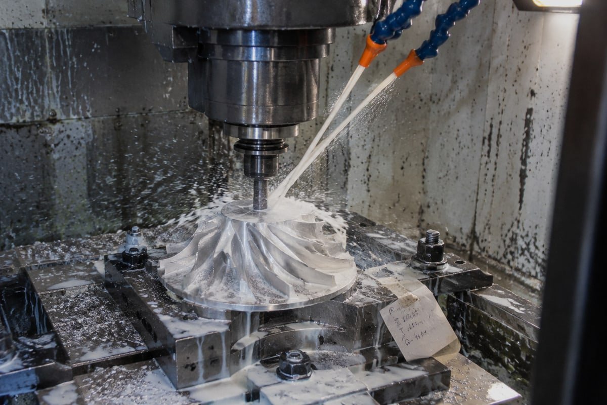
Machining capabilities are not a single number. They are a range that shifts with every variable on the part. Our milling cells run 3-axis, 4-axis, and 5-axis machines 3, and on selected features we reach 0.01–0.005 mm. Yet I would never promise that on a thin-wall titanium bracket with critical features on four faces. The difference between "achievable once" and "repeatable across a batch" is the whole story.
Capability by tolerance tier
| Tolerance tier | Typical limit | Usual process | Usual inspection |
|---|---|---|---|
| General | ±0.127 mm / ±0.005 in | Standard milling or turning, one setup | Calipers, height gauge |
| Precision | ±0.025 mm / ±0.001 in | Finishing passes, reaming, boring, in-process probing | Micrometer, bore gauge, pin gauge |
| High precision | ±0.01 mm | Rigid 5-axis setup, controlled feeds, temperature management | CMM inspection, functional gauges |
| Ultra precision | ±0.005 mm and below | Grinding, honing, lapping, wire EDM | Climate-controlled CMM, 100% inspection |
Material changes the answer
A tolerance we hold in 6061 aluminum 4 does not transfer automatically to 316 stainless, PEEK, or hardened tool steel. Aluminum machines fast but shows noticeable thermal expansion and can distort in thin sections. Stainless steel work-hardens and wears tools faster, so dimensional accuracy 5 drifts across a long run unless we monitor offsets. Engineering plastics absorb moisture and creep. Titanium builds heat at the cut. Hardened steels often need grinding or EDM to reach final size. Castings and weldments can release residual stress mid-cut and move after the part leaves the fixture.
Geometry and temperature
Thin walls deflect under cutting force. Deep pockets limit tool access. Long slender shafts flex. Parts needing several setups add datum-transfer error at each flip. Large parts grow and shrink with room temperature, and so does the measuring equipment. For tight limits on big aluminum parts, we ask customers to state the inspection temperature on the drawing. Otherwise a part that passes on our CMM at 20 °C may read differently on a warm shop floor overseas.
The practical lesson: ask the supplier to confirm capability for your actual feature, material, and quantity, not for a tolerance chart in general.
How do tighter tolerances affect my manufacturing cost and lead time?
Every time we quote a ±0.01 mm bore, we weigh a second finishing pass against slower feeds, probing cycles, and a CMM check before shipment.
Tighter tolerances raise cost and lead time because they change the process, not just the number. Each step tighter can add finishing passes, extra setups, grinding or EDM, temperature control, and 100% CMM inspection, while scrap risk climbs. Below ±0.025 mm, expect a different cost category entirely.

The manufacturing cost impact of a tight tolerance is rarely caused by the number itself. It comes from what we must do to hit it and prove it. Let me make that concrete.
How one feature climbs the cost ladder
| Tolerance on a 20 mm bore | What changes on the shop floor | Effect on cost and lead time |
|---|---|---|
| ±0.10 mm | One milling operation, standard tooling | Baseline, fits a 5-day lead time |
| ±0.05 mm | Slower finishing pass, tool-wear checks | Small increase in cycle time |
| ±0.02 mm | Reaming or boring, in-process probing, bore gauge on every part | Added operation and inspection time |
| ±0.01 mm | Rigid fixture, temperature-stable shop, CMM report, possible sorting | Noticeable cost step, longer schedule |
| ±0.005 mm | Grinding or honing after machining, process qualification, 100% inspection | Different process and cost category |
Published supplier data suggests only about 1% of parts truly need tolerances in the ±0.0002–±0.0005 in range. That matches our order book. Ultra-tight work is the exception, and it should be priced and scheduled as one.
Objections I hear, and how I answer them
"Tight tolerances mean quality." They mean predictability on that feature. They do not fix surface roughness, flatness, or a bad datum. A ±0.005 mm bore that is tilted still fails the bearing.
"Then loosen everything." A loose part that leaks, vibrates, or misaligns costs more than the savings. Rework, sorting, and warranty claims erase the discount quickly.
"Just use your shop's default." Our standard tolerances reflect proven capability. But they cannot replace a functional analysis of your assembly.
"Specify ultra-precision to be safe." That forces grinding and climate-controlled inspection without solving the real design risk. It also invites inspection disputes.
Finishing adds a hidden layer
Anodizing, plating, passivation, and heat treatment all move dimensions. We ask every customer whether tight limits apply before or after finishing. Masking, machining allowance, or a stated coating thickness avoids a part that passes machining and fails after anodizing. Widening non-critical limits also cuts cycle time and energy, which is why some buyers now call it sustainable tolerancing.
Which tolerance standards should I specify when sending drawings to a CNC machining factory?
The hardest drawings we receive are not the tightest ones. They are those with no title-block tolerance, mixed units, and hole positions chained from a cosmetic edge.
Specify ISO 2768 (usually -mK) as the general title-block tolerance, ISO 286 fit designations such as H7/g6 or H7/p6 for cylindrical interfaces, and GD&T per ASME Y14.5 or ISO 1101 for position, flatness, and perpendicularity. State units, datums, surface roughness, and whether dimensions apply before or after finishing.

Our engineers quote faster and more accurately when the drawing speaks a standard language. Here is how I recommend using each one.
The standards that belong on a CNC drawing
| Standard | What it controls | When we recommend it |
|---|---|---|
| ISO 2768 | General linear, angular, and geometric tolerances for untoleranced dimensions | Every drawing. ISO 2768-m for general machining, -c for cosmetic parts, -f only for small precise parts |
| ISO 286 | Standardized hole-and-shaft fits (H7/g6, H7/p6, H7/s6) | Bearings, dowels, bushings, pulleys, any clearance and interference fits |
| ASME Y14.5 | GD&T standards used mainly in North America | Position, flatness, perpendicularity, runout, profile |
| ISO 1101 | International geometrical product specification | Same purpose for European and Asian customers |
| Supplier capability sheet | The shop's standard, precision, and ultra-precision ranges | A reality check against the drawing before release |
Why GD&T beats a pile of ± dimensions
A ± size tolerance controls size only. A hole can be the right diameter and still sit in the wrong place or at the wrong angle. Consider a dowel-pin pattern. Four holes, each at ±0.02 mm from a corner edge, can all pass and still refuse to mate with the other plate. A single position tolerance referenced to the real functional datums describes the allowable zone far better. It also gives us more room to machine, because position zones are round, not square.
The same logic applies to our bearing housings. The bore size needs ISO 286. The bore axis needs perpendicularity to the mounting face. The pattern needs position. Surface roughness on the bore needs its own Ra value. Four callouts, four different controls.
Specify the fit, not just a small number
For cylindrical interfaces, state the fit class. H7/g6 gives controlled clearance for a sliding guide. H7/p6 or H7/s6 gives interference for a press-fit bushing. The right choice depends on load, temperature, lubrication, and how the parts are assembled. We would rather see the fit and the mating part than guess from a bare ±0.005 mm.
A metrology-first drawing checklist
Put datums on rigid surfaces that a CMM probe or gauge can actually reach. Give units. Give the general tolerance. Mark critical-to-function features. State material grade, heat-treatment condition, and coating thickness. Say whether tolerances apply before or after finishing. Add inspection requirements, such as a first-article report or a sampling plan. Then send the file. Our DFM feedback catches unreachable features, thin-wall risks, and tolerances that cannot be measured before a single chip is cut.
Conclusion
Over-tight tolerances drain budgets; loose ones break assemblies. Target precision where function demands it, loosen the rest, and send us your drawing for DFM feedback before release.
Footnotes
1. NIST is a primary authority for manufacturing standards and precision measurement guidelines in the United States. ↩︎
2. Wikipedia provides a technical overview of engineering tolerances, including unilateral and bilateral limit definitions. ↩︎
3. This reference explains the capabilities and technical operation of multi-axis CNC machines for high-precision manufacturing. ↩︎
4. ASM International provides authoritative data on the properties and machining characteristics of aluminum alloys like 6061. ↩︎
5. ScienceDirect offers peer-reviewed scientific context on factors that influence dimensional accuracy in precision engineering. ↩︎

 ไทย
 English
 Italiano
 Français
 日本語
 Deutsch (Sie)
 Español
 Русский
 العربية
 Български
 Čeština
 Dansk
 Suomi
 עִבְרִית
 हिन्दी
 Nederlands
 Português
 Română
 Slovenčina
 Svenska
 Tiếng Việt
 Türkçe
 Slovenščina