
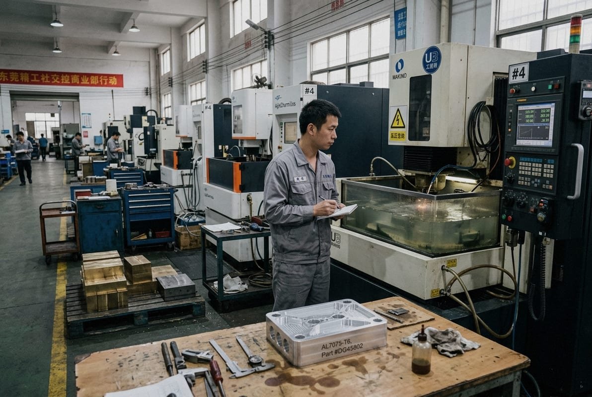
Every week, our engineering team in Dongguan reviews drawings from buyers who have parts that conventional milling simply cannot handle — ultra-hard tool steels, razor-thin walls, or intricate internal profiles that would snap any end mill.
Wire EDM machining is a non-contact electrical discharge machining process that uses a thin, electrically charged wire to cut conductive materials through controlled spark erosion, producing stress-free precision parts with tolerances as tight as ±0.005 mm, even in hardened metals that resist traditional cutting tools.
Below, I will walk you through exactly how the wire EDM process works, which materials it handles best, what tolerances and surface finishes you can realistically expect, and when it makes more sense than CNC milling. Every answer draws on our two decades of hands-on experience running wire EDM machines alongside 3-axis through 5-axis CNC centers.
How does the wire EDM process maintain extreme accuracy for my complex metal parts?
A US-based aerospace buyer once sent us a titanium bracket drawing with internal slots only 0.25 mm wide and a positional tolerance of ±0.01 mm — the kind of feature that makes traditional tooling irrelevant. That project taught our team exactly why wire EDM excels where other methods fail.
Wire EDM maintains extreme accuracy by using CNC-controlled spark erosion with a continuously fed brass wire, a stable dielectric fluid bath, and real-time tension monitoring, eliminating mechanical contact forces that cause deflection, vibration, and dimensional drift in complex metal parts.
The Science Behind the Spark
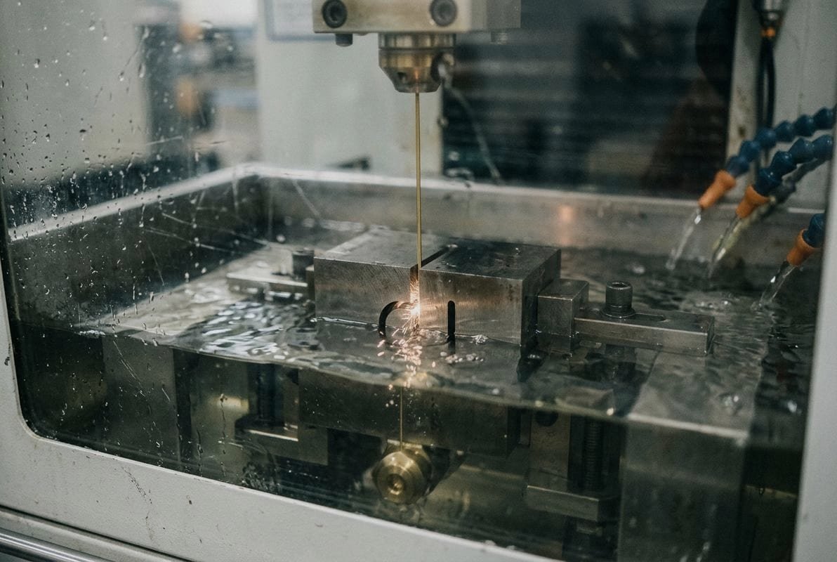
Wire EDM removes material through rapid electrical discharges 1 — roughly one million sparks per second — between a thin wire electrode and the workpiece. The wire, typically brass and 0.10–0.30 mm in diameter, never touches the metal. Instead, a plasma channel 2 forms across a tiny spark gap when voltage exceeds the dielectric breakdown threshold of the deionized water 3 surrounding the cut zone. Each spark reaches 8,000–12,000 °C, vaporizing microscopic particles about 2 microns in size.
Because there is zero physical contact, the process introduces no cutting forces, no tool deflection, and no vibration. That is the single biggest reason wire EDM holds such tight tolerances on complex geometries.
Step-by-Step: How We Run a Wire EDM Job
- CAD import. We load the customer's 2D or 3D model into our CAM software.
- CNC programming. Toolpaths are generated based on the geometry, wire offset, and number of skim passes.
- Workpiece setup. The part is fixtured and submerged in temperature-controlled deionized water — the dielectric fluid that insulates, cools, and flushes debris.
- Starter hole. If the cut is internal, a small hole is drilled or pre-existing from the design.
- Cutting. The charged wire follows the programmed path under precise CNC control. Thousands of sparks per second erode the metal along the contour.
- Skim passes. After the roughing cut, one or more finishing passes refine the surface finish and tighten dimensions.
Why Accuracy Stays Consistent
| Accuracy Factor | How Wire EDM Addresses It |
|---|---|
| Tool wear | Wire feeds continuously; fresh wire always contacts the spark zone |
| Vibration | Non-contact cutting — no lateral forces on the workpiece |
| Thermal distortion | Dielectric fluid cools the cut zone; spark duration is microseconds |
| Dimensional drift | CNC servo feedback adjusts wire position in real time |
| Complex profiles | Multi-axis wire guides tilt for tapered and 3D contours |
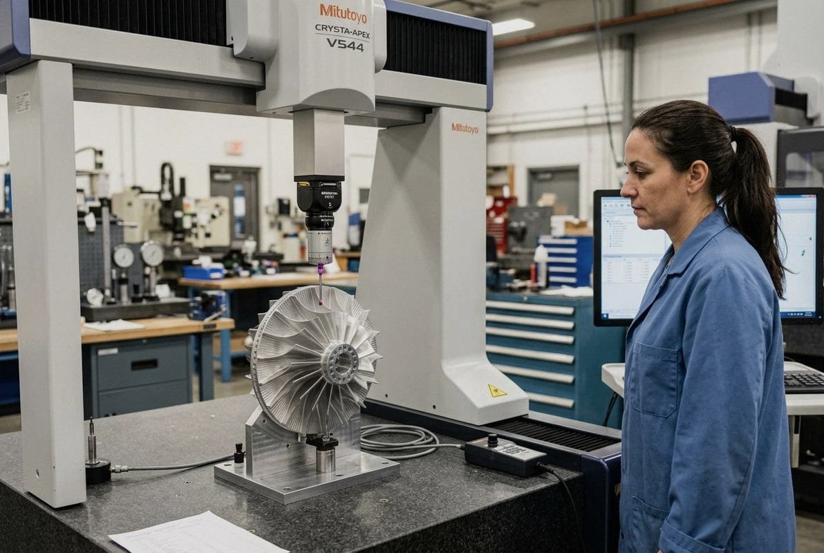
On our shop floor, we verify accuracy with CMM inspection after every first article. The combination of continuous fresh wire, adaptive CNC control, and dielectric cooling is what lets us consistently hit ±0.005 mm on production runs — not just on a single sample.
Which conductive materials are best suited for my wire EDM machining requirements?
One lesson we learned early — and have reinforced over 20 years — is that the hardness of a metal barely matters to a wire EDM machine. What matters is electrical conductivity. A Rockwell 62 HRC hardened D2 tool steel cuts almost as easily as soft aluminum because spark erosion does not rely on mechanical shear.
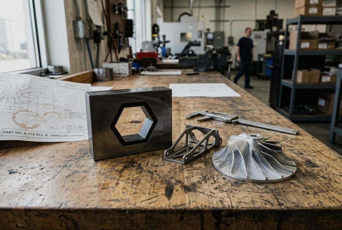
Any electrically conductive metal is suitable for wire EDM machining, but the best-suited materials include tool steels, hardened stainless steels, titanium, tungsten carbide, Inconel, and pre-hardened mold steels — metals that are extremely difficult or impossible to machine with conventional cutting tools.
Common Materials We Process on Wire EDM
| Material Category | Typical Grades | Why Wire EDM Is Ideal |
|---|---|---|
| Tool steel | D2, A2, M2, S7 | Cuts after heat treatment 4; avoids warping from re-hardening |
| Ruostumaton teräs | 304, 316L, 17-4 PH | Handles work-hardened or precipitation-hardened conditions |
| Titanium alloys | Ti-6Al-4V, Grade 2 | No tool wear; no reactive chip hazards |
| Tungsten carbide 5 | WC-Co composites | Too hard for milling; EDM vaporizes carbide easily |
| Copper & brass | C110, C360 | Excellent conductivity; fine detail for electrodes |
| Aluminum alloys | 6061-T6, 7075-T6 | Fast cutting; great for rapid prototyping |
| Superalloys | Inconel 718, Hastelloy | Resistant to conventional machining; EDM ignores toughness |
| Alloy steels | 4140, 4340 | Precision after case hardening |
Material Conductivity and Cutting Speed
Not every conductive material cuts at the same speed. The material removal rate depends on the melting point, thermal conductivity, and electrical resistivity of the workpiece. Aluminum, for example, cuts faster than tungsten carbide because it melts at a lower temperature and conducts heat more readily.
When our customers send drawings without specifying a material, we often recommend grades based on the part's end use. For mold making, we lean toward pre-hardened P20 or H13. For aerospace components, Ti-6Al-4V or Inconel 718 are common. For prototype brackets and housings, 6061-T6 aluminum keeps costs down and delivery fast.
What About Non-Conductive Materials?
Wire EDM cannot process plastics, ceramics, glass, or composites — at least not with standard commercial equipment. Some research labs have explored assisted methods for insulating ceramics, but these techniques are not production-ready. If your part requires both conductive and non-conductive features, we can machine the conductive portions on wire EDM and handle the rest on our CNC milling or turning centers as part of a one-stop solution.
The bottom line: if the material conducts electricity, wire EDM can cut it — regardless of hardness. That opens the door to hardened materials that would destroy conventional cutting tools within seconds.
What specific tolerances and surface finishes can I achieve for my precision components?
A medical device 6 buyer in Europe recently asked us to hold ±0.005 mm on a 17-4 PH stainless steel implant guide and deliver a surface roughness of Ra 0.4 µm — with no secondary polishing. We ran four skim passes on the wire EDM and met both specs on the first article. That kind of result is routine when the process parameters are dialed in correctly.
Wire EDM typically achieves tolerances of ±0.005 mm to ±0.01 mm and surface finishes from Ra 0.2 µm to Ra 1.6 µm, depending on the number of skim passes, wire diameter, and material type, often eliminating the need for grinding or polishing on precision components.
Tolerance Ranges by Application
Tolerances on wire EDM are controlled primarily by three things: machine rigidity, CNC resolution, and the number of passes. A single roughing cut might hold ±0.02 mm. Add one or two skim (finishing) passes and you tighten that to ±0.01 mm. Push to three or four skim passes and you reach ±0.005 mm or better.
| Pass Type | Typical Tolerance | Typical Surface Finish (Ra) | Primary Purpose |
|---|---|---|---|
| Rough cut (1st pass) | ±0.02–0.03 mm | Ra 2.5–3.2 µm | Bulk material removal |
| First skim pass | ±0.01–0.015 mm | Ra 1.0–1.6 µm | Dimensional refinement |
| Second skim pass | ±0.005–0.01 mm | Ra 0.4–0.8 µm | Fine tolerance and finish |
| Third / fourth skim pass | ±0.003–0.005 mm | Ra 0.2–0.4 µm | Mirror-like finish; tightest tolerance |
Factors That Affect Your Final Tolerance
Several variables influence whether you land at the tight or loose end of these ranges:
- Wire diameter. Thinner wires (0.10 mm) cut finer features but may limit speed. Thicker wires (0.25–0.30 mm) are faster but leave a larger kerf.
- Material stability. Internal stresses in the workpiece can cause slight movement after cutting. Stress-relieved or annealed stock holds tolerance better.
- Part thickness. Thicker workpieces (above 100 mm) may see slight taper or barreling. Wire tilt compensation corrects much of this.
- Dielectric temperature. We monitor and control the deionized water temperature to within ±1 °C. Fluctuations cause thermal expansion in both the machine and the part.
- Fixture rigidity. A poorly fixtured part will shift under the flushing pressure of the dielectric fluid, degrading accuracy.
Surface Finish: Why Skim Passes Matter
Each skim pass uses lower energy and removes only a few microns of material. The result is a progressively smoother surface. For many customers, a two-pass finish (Ra 0.8 µm) is sufficient and keeps cost down. For applications like mold cavities or sealing surfaces, we go to three or four passes to reach Ra 0.2–0.4 µm. At that level, the surface is nearly mirror-like, and secondary finishing operations are often unnecessary.
In our ISO 9001:2015 7-certified inspection process 8, we verify both dimensional tolerances using a CMM and surface roughness using a profilometer before shipping. Each shipment includes an inspection report so you know exactly what you are receiving.
When should I choose wire EDM over traditional CNC milling for my custom manufacturing project?
During a recent quoting session, a US automation equipment company sent us two versions of the same bracket: one redesigned for milling and one with the original geometry that required internal keyways, sharp transitions, and hardened H13 steel. The milling version added four extra features to accommodate tool access. The wire EDM version kept the original elegant design — and cost less. That trade-off is the core of the milling-versus-EDM decision.
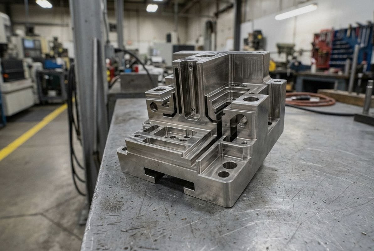
Choose wire EDM over CNC milling when your parts involve hardened materials above 45 HRC, intricate internal profiles, extremely tight tolerances below ±0.01 mm, thin walls prone to deflection, or complex geometries that conventional cutting tools cannot physically reach.
Quick Decision Matrix
Before diving into detail, here is a practical comparison to help you decide at a glance:
| Decision Factor | Wire EDM | CNC-jyrsintä |
|---|---|---|
| Material hardness | Any conductive metal, any hardness | Best below ~45 HRC; above that, tool wear spikes |
| Feature type | Through-profiles, internal slots, fine contours | Pockets, 3D surfaces, open cavities |
| Suvaitsevaisuus | ±0.003–0.01 mm typical | ±0.01–0.025 mm typical |
| Surface finish | Ra 0.2–1.6 µm (skim passes) | Ra 0.4–3.2 µm (depending on tool and speed) |
| Part stress | Virtually zero mechanical stress | Clamping and cutting forces can distort thin parts |
| Speed on simple shapes | Slower; cutting speed is lower | Much faster for bulk removal |
| Speed on complex hard parts | Faster overall (no tool changes, no breakage) | Slower due to frequent tool changes and reduced feeds |
| Internal sharp corners | Limited by wire radius (~0.05–0.15 mm) | Limited by cutter radius (typically larger) |
| Pocketing / partial depth cuts | Not possible (through-cut only) | Fully capable |
| Setup cost | Moderate | Low to moderate |
Scenarios Where Wire EDM Wins
Hardened parts. If the design calls for D2 at 60 HRC or tungsten carbide, milling is impractical. Wire EDM cuts these hardened materials without tool wear.
Tight-tolerance internal features. Narrow internal keyways, spline profiles, and gear tooth forms are natural wire EDM work. The thin wire fits where end mills cannot.
Delicate or thin-walled components. Non-contact cutting means no clamping force and no lateral load. We have cut walls as thin as 0.3 mm in stainless steel without deflection.
Mold and die components. Mold making often requires precise through-profiles in hardened inserts. Wire EDM produces these in a single setup after heat treatment.
Scenarios Where CNC Milling Wins
Milling is the better choice for 3D freeform surfaces, pocketing, large material removal, and soft metals where speed matters most. If your part is a machined aluminum housing with pockets and counterbores, a 5-axis CNC mill will be faster and cheaper.
The Hybrid Approach
Many of the projects we handle at stcncmachining combine both processes. We rough-mill a block of steel, send it for heat treatment, then finish critical profiles on wire EDM. This hybrid workflow leverages the high material removal rate of milling and the precision of spark erosion, delivering the best balance of cost, speed, and accuracy.
Our team evaluates every incoming drawing with DFM feedback that considers both milling and EDM capabilities. If wire EDM adds cost without adding value, we will tell you. If it saves a redesign or eliminates a grinding step, we will recommend it. That honest engineering conversation is part of what keeps our long-term customers coming back.
Päätelmä
Wire EDM machining 9 delivers unmatched precision on hard, conductive metals and complex profiles where traditional milling falls short. Whether you need tight tolerances, fine surface finishes, or intricate geometries, our team at stcncmachining is ready to help — reach out with your drawings for a fast DFM review and quote.
Footnotes
1. Explains the fundamental mechanism of EDM. ↩︎
2. Explains the fundamental physics of plasma. ↩︎
3. Provides information on the properties and uses of deionized water. ↩︎
4. Describes industrial heat treatment processes for metals. ↩︎
5. Details the properties of tungsten carbide. ↩︎
6. Official FDA resource on medical device regulations. ↩︎
7. Official information on the ISO 9001:2015 quality management standard. ↩︎
8. Official ISO 9001 quality management guidelines. ↩︎
9. Explains the fundamental process of Wire EDM. ↩︎

 Suomi
Suomi  English
  Italiano
  Français
  日本語
日本語  Deutsch (Sie)
  Español
  Русский
  العربية
  Български
  Čeština
  Dansk
Dansk  עִבְרִית
  हिन्दी
  Nederlands
  Português
  Română
  Slovenčina
  Svenska
  ไทย
ไทย  Tiếng Việt
  Türkçe
  Slovenščina