
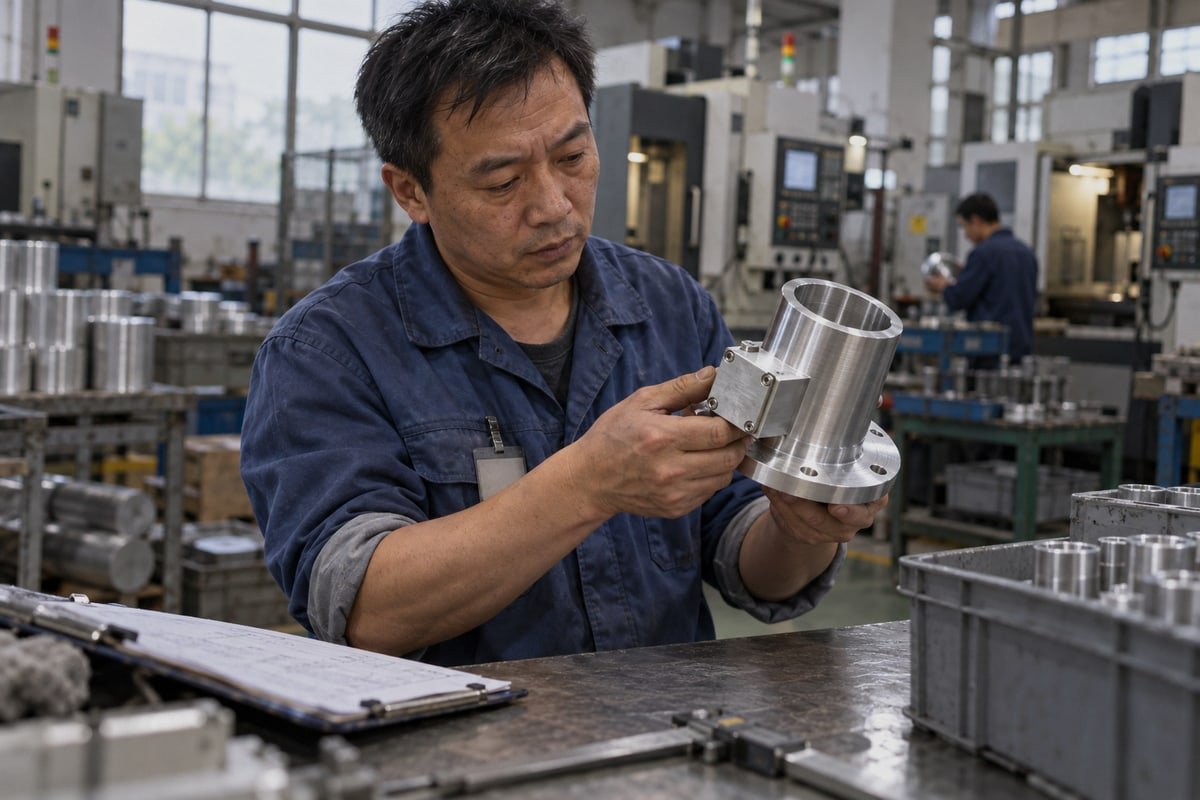
[Quality problems in CNC projects](https://stcncmachining.com/?p=15361) rarely start at the machine. On our Dongguan production line, rejects usually trace back to unclear drawings or unchecked material. Layered checks prevent that.
To avoid quality problems in CNC projects, confirm the supplier understands your drawings, verify material with mill certificates, approve a first article before batch production, and require incoming inspection, in-process QA, and 100% outgoing inspection backed by documented reports.
Each of those steps answers a question buyers ask us every week. Below I walk through the four that matter most, in the order they happen on a real order.
How can I identify CNC suppliers who truly understand my technical drawings before placing an order?
A German engineer once sent us a drawing with dense GD&T callouts and asked one question: which ones would we challenge? That question told me he had been burned before.
Identify suppliers who understand your drawings by sending a sample drawing and judging the reply: a capable shop returns DFM feedback within days, questions specific tolerances, datums, and threads, confirms the drawing revision, and explains how each critical dimension will be measured.
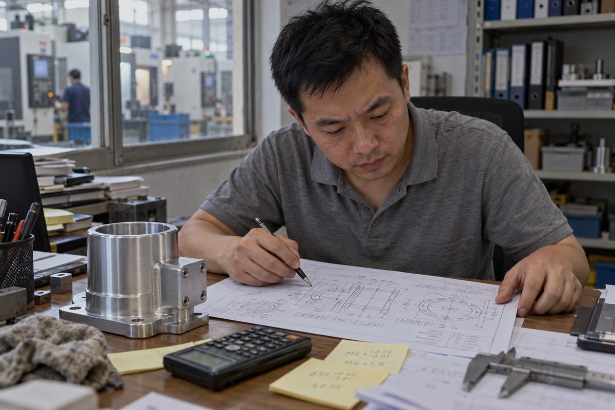
The fastest way to test a supplier is to give them a real drawing before you give them a purchase order. Not a simple bracket. Pick a part with a datum structure, a thread, a surface finish callout, and one tight tolerance. Then read the reply carefully. The quote price matters less than the questions that come with it.
Why drawing confusion causes quality problems in CNC projects
Most quality problems in CNC projects begin at the quoting stage. A salesperson without an engineering background reads "Ra 0.8" as a cosmetic note. A programmer reads a true-position callout as a simple hole diameter. The part gets made, the diameter is fine, and the hole is still in the wrong place. In our experience exporting to Germany and the US, the drawing review is where we catch the most expensive mistakes, long before any CAD/CAM simulation starts.
Signals to look for in the first reply
| What you see in the reply | What it tells you |
|---|---|
| Questions about Geometric Dimensioning and Tolerancing datums or feature relationships | The team reads tolerances as function, not just numbers |
| A note that a tolerance is tighter than the feature needs | They understand cost and will not quietly loosen it later |
| Confirmation of drawing revision 1 and material condition | Revision control exists |
| A statement of how each critical dimension will be inspected | Measurement was planned, not improvised |
| A single price with no mention of threads, deburring, or coating | Hidden costs are likely to appear later |
Certification is a baseline, not proof
Buyers often tell me, "You are ISO 9001:2015 2 certified, so the parts will be fine." I understand the logic, but a certificate shows a management system exists. It does not read your drawing. Our factory holds that certification, and we still run a DFM review on every uploaded drawing because the certificate never caught a misread thread spec. Ask for the certificate, then ask for the DFM feedback. Judge the second one harder.
One more practical check: ask the supplier which features they would machine in a second setup. If they cannot answer, they have not yet thought about your part.
What quality documents and inspection reports should I request to avoid unpleasant surprises?
Years ago we shipped optical housings with a perfect dimensional report but no material certificate. The customer's QA held the shipment. That lesson shaped our document pack.
Request a first article inspection report, a dimensional inspection report for critical features, a material certificate with heat or lot number, surface finish and coating records, a final outgoing inspection report, and the nonconformance procedure, all tied to the drawing revision number.
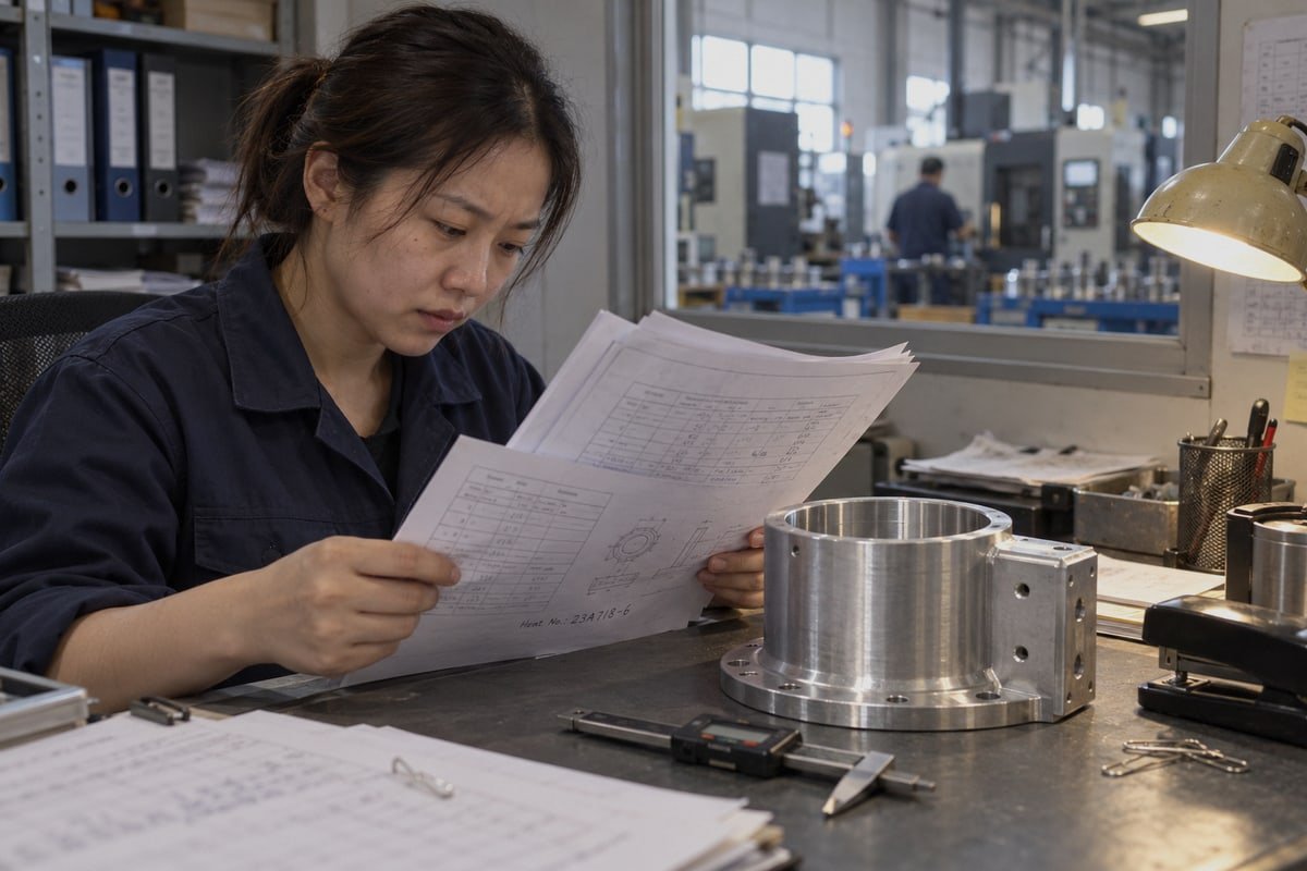
Documents do two jobs. They let your internal acceptance process run without delay, and they let both sides trace a problem to its cause. A report that cannot be linked to a drawing revision and a material lot does neither job. So the first thing I check on any report is the header, not the numbers.
Match each document to a specific risk
| Document | Risk it covers | When to request it |
|---|---|---|
| First article inspection report | Wrong offsets, tools, or program before batch | After the first piece, before batch release |
| Dimensional inspection report | Dimensional accuracy of critical features | With samples and with each batch |
| Material certificate with heat or lot number | Wrong alloy or grade substitution | Before machining starts |
| Surface finish and coating record | Ra values, anodize thickness, color consistency | With finished parts |
| Final outgoing inspection report | Burrs, threads, cosmetic defects, cleanliness | Before shipment |
| Nonconformance and corrective action record | Repeat defects being "fixed" by offset changes only | Whenever a reject occurs |
Ask how the numbers were produced
A dimensional report is only as good as the instrument behind it. A ±0.005 mm bore measured with calipers is not a measurement. It is a guess. For our tightest work, which reaches 0.01 to 0.005 mm on 3-axis, 4-axis, and 5-axis parts, we rely on a Coordinate Measuring Machine for positional and geometric features and precision gauges for simple sizes. Ask the supplier to name the instrument next to each critical dimension. If every feature says "caliper," the report is not telling you much.
Surface finish deserves the same treatment. Surface Finish Standards like Ra are measurable, so the report should show a measured value, not the word "smooth." Coating records should show thickness and the process used, because anodize color drift and peeling are among the most common complaints we hear from buyers switching suppliers.
More paper is not more quality
Some buyers ask for a full report on every feature of every part. That turns inspection into expensive containment. Inspection detects problems; it does not prevent them. We prefer a risk-based pack: full data on critical-to-function features, sampling on the rest, and 100% outgoing inspection for visual, thread, and burr checks. That is the combination that catches real defects without doubling the inspection time.
How do I prevent dimensional drift and defects when moving from samples to batch production?
During one 6061 bracket run, sizes started drifting after a few hundred pieces. The program was fine. The end mill was wearing, and only our in-process chart caught it.
Prevent dimensional drift from sample to batch by locking the validated process: freeze the program, fixture, and tool list, set tool-life replacement limits, compensate for thermal changes, run first article inspection, measure critical dimensions at fixed intervals, and perform 100% outgoing inspection.
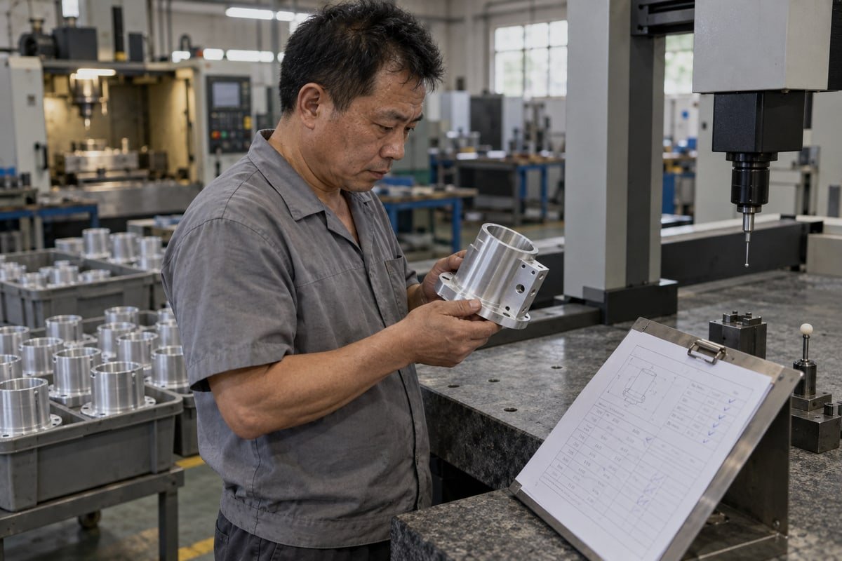
Samples pass and batches fail for a simple reason. A sample is made under the best conditions a shop has. The best operator runs it. The tool is fresh. The machine is warm but not hot. The operator adjusts offsets by hand until the part is right. Batch production removes all of those advantages unless the process is written down and controlled.
Where drift comes from and what stops it
| Drift source | What it looks like | Control we apply |
|---|---|---|
| Tool wear | Sizes grow or shrink slowly across the batch | Tool-life counters and scheduled replacement cycles, not operator judgment alone |
| Thermal drift | Morning parts and afternoon parts differ | Warm-up cycles and offset compensation as shop temperature changes |
| Tool Deflection | Tapered walls, undersize deep pockets | Shorter tool projection, lighter finishing passes |
| Workholding Stability | Random outliers, thin walls springing after unclamping | Rigid fixtures, support under thin sections, controlled clamp force |
| Machine condition | Backlash, squareness errors | Preventive Machine Maintenance with periodic geometry and spindle checks |
| Cutting parameters | Chatter marks, burrs, heat | Feeds and Speeds Optimization validated per material and setup |
Our in-process QA sequence
- Freeze the program revision, setup sheet, and tool list after the first article is approved.
- Measure the first piece of every setup and every tool change against the drawing.
- Check critical dimensions at fixed intervals, with the interval set by tolerance and tool life.
- Record every offset change and tool change, so a trend can be seen, not just a reject.
- Stop the machine on unusual noise, chip color, or finish, and investigate before continuing.
- Run 100% outgoing inspection for visual, thread, and burr condition before packing.
Monitoring beyond the micrometer
Larger runs justify extra sensing. Spindle load and torque monitoring can show tool chipping that the eye never sees. Some shops map resonance with Frequency Response Function 3 testing to find spindle speeds that trigger chatter and simply avoid them. Thermal compensation that adjusts offsets through the day is becoming common in precision work. These tools help, but they do not replace a trained operator. Automation can repeat a bad offset across an entire batch just as faithfully as a good one.
Buyers sometimes suggest that slower cutting is the safe answer. It often is not. Slowing a feed can increase rubbing and heat, which makes drift worse. The right answer depends on what is actually unstable.
What steps can I take to ensure consistent material quality and avoid substitution issues in my CNC parts?
Every quote forces a choice: cheapest bar stock 4 or traceable stock with a mill certificate. We choose traceable. The premium is smaller than one returned 316 part from Europe.
Ensure consistent material quality by specifying the exact alloy, temper, and standard on the drawing, requiring a mill certificate with heat number per lot, confirming incoming inspection with hardness or spectrometer checks, keeping lot traceability on each batch, and auditing the supplier's stock sources.

Material problems are the quietest quality problems in CNC projects. A part made from the wrong alloy can pass every dimensional check and still fail in service. The corrosion shows up months later, or the thread strips under load, or the anodize comes out blotchy. By then the batch is installed in equipment. So material control has to happen before the first chip is cut, which is exactly why incoming inspection is the first of our three QC stages.
Where substitution actually happens
| Specified material | Common substitute | What goes wrong | How to catch it |
|---|---|---|---|
| 6061-T6 aluminum | Unspecified or recycled aluminum | Lower strength, poor anodize color | Certificate check plus hardness test |
| 316 stainless steel | 304 stainless steel | Pitting in chloride or marine environments | Composition verification, molybdenum content |
| PEEK | Cheaper engineering plastic | Loss of temperature and chemical resistance | Certificate, density, and color check |
| Alloy steel, specified temper | Wrong heat treatment condition | Dimensional change after machining, wrong hardness | Hardness check before and after machining |
Put the material on the drawing, not in the email
Emails get lost. Drawings travel with the order. Write the alloy, temper, and standard on the drawing title block. If the part needs 316 rather than 304, say why, because a supplier who understands the reason will not treat the grades as interchangeable. We machine aluminum, stainless, brass, copper, titanium, tool steel, and plastics such as POM, PEEK, and PPSU, and the grade question comes up on nearly every quote. Clear callouts shorten that conversation.
Fingerprint each lot
Material Machinability varies even within the correct grade. Two lots of the same aluminum can differ in hardness enough to change burr behavior and surface finish. The practice some call batch fingerprinting is simple: check hardness and, where it matters, chemistry on each new lot, record the lot number against the batch, and adjust cutting parameters if the material behaves differently. On our incoming inspection we compare stock to the certificate, verify dimensions and surface condition, and log the lot number so every finished batch traces back to a specific heat. For high-risk stainless or titanium jobs, we can arrange third-party composition testing on request.
Audit the source, not just the paperwork
A certificate can be copied. Ask your supplier where their bar stock comes from and whether they buy from mills or from traders. Ask to see the lot number on the raw stock photo for your job. A supplier who already does this will answer in minutes.
Päätelmä
Quality problems in CNC projects are costly but preventable. Define requirements, verify material, approve a first article, and insist on incoming, in-process, and 100% outgoing inspection.
Footnotes
1. Overview of revision control systems used to ensure engineering drawings and quality reports match the correct design version. ↩︎
2. Official international standard for quality management systems mentioned as a baseline for CNC supplier certification. ↩︎
3. Technical explanation of frequency response analysis used to identify and avoid machine resonance and chatter during production. ↩︎
4. Scientific overview of metal bar stock production and its role as raw material in precision engineering. ↩︎

 Suomi
 English
 Italiano
 Français
 日本語
 Deutsch (Sie)
 Español
 Русский
 العربية
 Български
 Čeština
 Dansk
 עִבְרִית
 हिन्दी
 Nederlands
 Português
 Română
 Slovenčina
 Svenska
 ไทย
 Tiếng Việt
 Türkçe
 Slovenščina