

Every week a drawing lands on our Dongguan shop floor that will cost double to machine. Nobody asked how to design CNC parts for better manufacturability before releasing it.
To design CNC parts for better manufacturability, meet assembly needs first, then remove every feature that adds cost: tight tolerances, sharp internal corners, deep narrow pockets, thin walls, undercuts, and extra setups. Use standard tools and get DFM feedback before release.
That is the whole philosophy in one sentence. The rest of this article breaks it into four practical questions. I will show you what to avoid, how to set tolerances, which materials and wall thicknesses cause trouble, and how to get a DFM review before you lock the design.
What Design Features Should I Avoid to Reduce CNC Machining Difficulty?
Last year a housing drawing came in with sharp 90-degree pocket corners and a 40 mm deep slot only 6 mm wide. The quote jumped before we cut any metal.
Avoid sharp internal corners, pockets deeper than four times their width, walls thinner than 0.8 mm in metal, undercuts, non-standard holes, freeform surfaces, and features that need more than two setups. Each one forces special tools, longer cycle times, or extra operations.

Our starting point for any design review is simple. If a feature does not help the part assemble or function, and it makes machining slower, more precise, or adds a process step, we flag it. Here are the features that trigger that flag most often.
Why sharp internal corners cost you money
A milling cutter is round. It cannot cut a square inside corner. If your drawing demands one, we have two choices. We can use a tiny cutter and crawl around the corner, or we send the part to Wire EDM 1 as a second operation. Both add time. The fix is easy. Specify internal corner radii at least 10% larger than the radius of the cutter you expect us to use. A 10 mm cutter has a 5 mm radius, so draw a 5.5 mm or 6 mm corner radius. That small margin lets the tool sweep through the corner in a smooth arc instead of stopping and reversing. The result is less chatter, longer tool life, and a cleaner wall. If a mating part truly needs a square corner, add a dog-bone relief or move the sharp corner to the mating part instead.
Deep pockets and tooling access
Depth is the second big cost driver. Keep pocket depth to no more than four times the pocket width. Several design guides also cite three to four times the cutter diameter as a practical cavity limit. Beyond that, we need long-reach tools. Long tools deflect, vibrate, and leave poor surface roughness. On the mold base in our photo library, every deep cavity was stepped so a larger cutter could rough the top section before a smaller one finished the bottom. Tooling access also means clearance for the tool holder, not just the tip. A tall wall next to a deep pocket can block the holder even when the cutter fits.
Undercut limitations and freeform surfaces
Undercuts need T-slot cutters, lollipop cutters, or a second orientation. Freeform surfaces need ball-nose finishing with fine stepovers. Both are legitimate when they serve a purpose. A buyer once pushed back on this point. He argued that one complex 5-axis part replaced three brackets and saved assembly labor. He was right, and we machined it on our 5-axis cell. The point is not that complexity is wrong. The point is that complexity should be a decision, not an accident of CAD modeling.
Features to avoid and what to use instead
| Feature to avoid | Why it hurts machinability | Cheaper alternative |
|---|---|---|
| Sharp internal corner | Needs tiny cutter or EDM | Radius 10% larger than cutter radius, or dog-bone relief |
| Pocket deeper than 4x width | Long tools deflect and chatter | Widen pocket, step the depth, or split the part |
| Undercut groove | Special cutter, extra setup | Two-piece assembly or relocate the groove |
| Features on five faces | Multiple setups and re-fixturing | Align features along one or two axes |
| Odd hole diameters | Interpolated instead of drilled | Standard drill sizes 2 and reamer sizes |
| Full freeform skin | Ball-nose finishing passes | Tangent planes or larger-radius blends |
One more rule applies to all of these. Align as many features as possible along a single primary axis. When everything is reachable from the top and one side, we can often finish the part in one or two fixturing and setups, and skip the probing and alignment that each extra orientation requires.
How Can I Choose Tolerances That Balance Precision and Cost?
Our 5-axis machines hold 0.01–0.005 mm on bores. We weigh that capability against cycle time every day, because holding it costs more hours than a ±0.05 mm feature.
Assign tight tolerances only to mating, sealing, or locating features. Use standard commercial tolerances everywhere else. Tie critical dimensions to datums you can actually fixture and probe. Then ask your machinist what their process holds routinely before you commit to a number.

Tolerances are the most common place where good engineers create expensive parts by accident. A tight tolerance block in the title corner is easy to type. It is not easy to machine. Here is how I think about it.
Build a tolerance hierarchy
Not every dimension on a part does the same job. We ask our customers to sort their dimensions into four groups before assigning numbers.
| Tolerance level | Typical application | What it costs us to hold |
|---|---|---|
| General | Non-mating edges, cosmetic faces, clearance pockets | Standard feeds and speeds, no extra checks |
| Functional | Bolt patterns, locating faces, slip fits | Careful tool selection, in-process measurement |
| Critical | Press fits, bearing bores, sealing surfaces | Finish passes, reaming or boring, temperature control, CMM report |
| Geometric | Position, flatness, perpendicularity, runout | Defined datums, dedicated fixturing, full GD&T inspection |
Published CNC references list broad default ranges, often around ±0.005 to ±0.030 inch, but those numbers shift with material, feature size, and machine. Treat them as a starting conversation, not a guarantee.
Make datums match the real assembly
GD&T standards work only when the datums are real. If datum A is a face that gets clamped during machining, we cannot probe it. If datum B is a cylindrical boss that sits inside a cavity, our CMM stylus may not reach it. Give us flat, unobstructed datum surfaces. Choose datums that the part actually rests on in your assembly. Then the drawing, the fixture, and the inspection all agree. This single habit removes most of the arguments between a buyer's incoming inspection and our outgoing report.
Treat surface roughness as a dimension
Surface roughness is a tolerance too. A Ra 0.8 finish needs slower feeds and finer stepovers than a Ra 3.2 finish. Specify it only on sealing, sliding, or cosmetic faces. Also remember that anodizing, plating, and bead blasting change dimensions. Tell us whether a bore tolerance applies before or after coating.
The objection: do tighter tolerances not reduce assembly variation?
They do. A buyer from the automotive side raised exactly this concern. His view was that tighter parts mean fewer assembly adjustments. I agree. The issue is where you spend the precision. Tighten the two bores that locate the sensor. Leave the outer envelope at ±0.1 mm. You get the assembly benefit on the features that matter, and you avoid paying for precision on faces that touch nothing.
Which Material and Wall Thickness Choices Affect My Part’s Manufacturability?
A German customer once asked us to machine a bracket in titanium for stiffness. After we compared cycle times, he switched to 7075 aluminum 3 and added two ribs.
Choose a material with good machinability whenever strength allows, such as 6061 aluminum, brass, or POM. Keep metal walls above 0.8 mm and plastic walls above 1.5 mm, support tall walls with ribs, and match stock size and grain direction to the finished part.
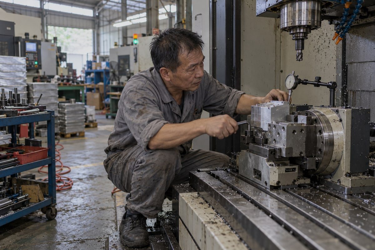
Material and wall thickness decide how fast we can cut and how often a part warps. They also decide how much of your budget goes to chips on the floor. Let me walk through both.
Material machinability is a cost multiplier
We machine aluminum, stainless steel, copper, brass, titanium, alloy steel, tool steel, and engineering plastics 4 such as ABS, POM, PEEK, nylon, PC, PPSU, and HDPE. The cost per kilogram of raw stock is only part of the picture. The bigger factor is how the material behaves under the cutter.
| Материал | Machinability (relative) | Common issues we manage | Good fit for |
|---|---|---|---|
| 6061 / 7075 aluminum | Very high | Burrs, distortion from residual stress 5 in thin sections | Housings, brackets, optical mounts |
| Месинг | Very high | Minimal; excellent finish | Fittings, electrical parts |
| Mild / alloy steel | Medium | Tool wear, heat | Shafts, fixtures, mold bases |
| 304 / 316 stainless | Low to medium | Work hardening, slow feeds | Medical, food equipment |
| Титан | Low | Heat, tool life, chatter | Aerospace, implants |
| POM / nylon | High | Thermal expansion during cutting | Gears, guides, wear parts |
| PEEK | Medium | Cost of stock, stress relief needed | High-temperature medical and electronic parts |
So if your part is a sensor housing that sees no structural load, 6061 aluminum 6 will machine three to four times faster than stainless and hold flatness better. If corrosion resistance drives the choice, 316 is right, but expect a longer quote and lead time.
Minimum wall thickness and why it is not a universal number
The widely cited minimum wall thickness is 0.8 mm for metals and 1.5 mm for plastics. We treat those as floors, not targets. A 0.8 mm aluminum wall that is 5 mm tall is fine. The same wall at 40 mm tall will ring like a tuning fork under the cutter and leave a wavy surface. Wall height, unsupported length, and material temper matter as much as thickness.
Thin walls are often necessary for weight or thermal reasons, and I will not tell a drone or medical device team to make everything thicker. Instead, do three things. Add ribs to break up long spans. Use non-uniform rib spacing or slightly varied wall thicknesses, which disrupts the harmonic resonance that causes chatter during high-speed milling. And add generous fillets where the wall meets the floor, so the cutter is not working into a stress riser.
Stock, grain, and leftover material
Pick a stock envelope close to your finished part. A 50 mm part cut from 60 mm plate wastes less time than the same part cut from 100 mm plate. For plates and wrought bars, orient load-bearing features along the rolling or forging grain direction. The machinist cannot fix grain orientation after the fact, so note it on the drawing. Finally, remember that residual stress in thick plate releases as we remove material. For precision flat parts we often rough, let the part relax, then finish. That is a process cost, and a symmetric design reduces it.
How Do I Get DFM Feedback Before Finalizing My CNC Design?
Twenty years of quoting taught us one thing: the cheapest change to a part happens before the drawing is signed. Afterwards every fix costs a revision cycle.
Send your 3D model, 2D drawing, material, quantity, and finish to a machining supplier that offers DFM review before quoting. Ask for comments on setups, tool access, tolerances, and alternatives. Then revise the model once, and release the drawing with those changes built in.

DFM for CNC machining is not a document we send after you place an order. It is a conversation that happens while the design is still soft. Here is how the process runs at our factory in Chang’an, and what you can do on your side to make it useful.
The DFM review process, step by step
- Send a complete package. We need the STEP file, the 2D drawing with GD&T, the material grade, the expected quantity, and any surface treatment. A model without a drawing leaves tolerances unknown. A drawing without quantity leaves fixturing and setups undecided.
- We check tool access first. Our engineers rotate the model and ask one question: can every important feature be reached by a standard tool while the part stays clamped? If the answer needs three or more orientations, we mark it.
- We check geometry against the cutter list. Internal corner radii, pocket depth, slot width, and minimum wall thickness are compared to the cutters we stock. Features under about 2.5 mm get a note, because they usually need micro tooling.
- We check holes and threads. We confirm standard drill sizes and thread forms. For thread depth, roughly twice the nominal diameter is usually enough for strength in metals. Three times the diameter is a practical upper limit before tapping risk climbs. Deeper than that, we suggest a through-hole or a thread insert, especially in plastics.
- We check inspection. Every critical dimension must be probe-accessible. If a datum cannot be touched on the CMM, we propose a different one.
- We send alternatives, not just objections. Each flag comes with a suggested fix and its effect on price and lead time. You decide. Often the revised part reaches our standard lead time of as short as 5 days instead of a two-week custom-fixture job.
What to tell your supplier about volume
The right answer changes with quantity. For a prototype we favor 3-axis machining, standard vise jaws, and tolerances that can shift quickly. For low-volume runs, soft jaws and a dedicated setup pay off. For mass production, we may suggest sacrificial clamping lugs that get cut off at the end, or a redesign that lets a robot load the part. Some customers now send near-net 3D-printed metal blanks for finishing. Those parts need specific machining allowances and clamping lugs designed in from the start, so tell us if a hybrid workflow is planned.
A short pre-release checklist
- Can the part be finished in one or two setups?
- Are internal radii larger than the cutter radius?
- Are pockets within four times their width in depth?
- Are walls supported, and above the minimum for the material?
- Are holes, threads, and counterbores standard?
- Are tight tolerances limited to mating features with real datums?
- Is the stock size available in the chosen grade?
- Has a machinist reviewed the model?
If you can answer yes to all eight, your drawing will quote faster and the first article will match the print. Our ISO 9001:2015 process then documents the result with a dimensional inspection report and material certificate, which keeps your incoming inspection simple.
Заключение
Expensive CNC parts usually start as avoidable drawing choices. Meet assembly needs, strip out cost-driving details, and let a DFM review catch the rest before you release.
Footnotes
1. Technical overview of the electrical discharge machining process used for creating sharp internal corners. ↩︎
2. Reference for standard drill bit dimensions used to optimize CNC hole-making operations. ↩︎
3. Peer-reviewed research on the mechanical properties and structural performance of 7075 aluminum alloys. ↩︎
4. National institute providing standards and data for engineering plastics and advanced materials. ↩︎
5. Scientific explanation of how residual stress in raw stock affects the stability of machined parts. ↩︎
6. Authoritative source for material properties and aerospace applications of 6061 aluminum alloys. ↩︎

 Български
 English
 Italiano
 Français
 日本語
 Deutsch (Sie)
 Español
 Русский
 العربية
 Čeština
 Dansk
 Suomi
 עִבְרִית
 हिन्दी
 Nederlands
 Português
 Română
 Slovenčina
 Svenska
 ไทย
 Tiếng Việt
 Türkçe
 Slovenščina