
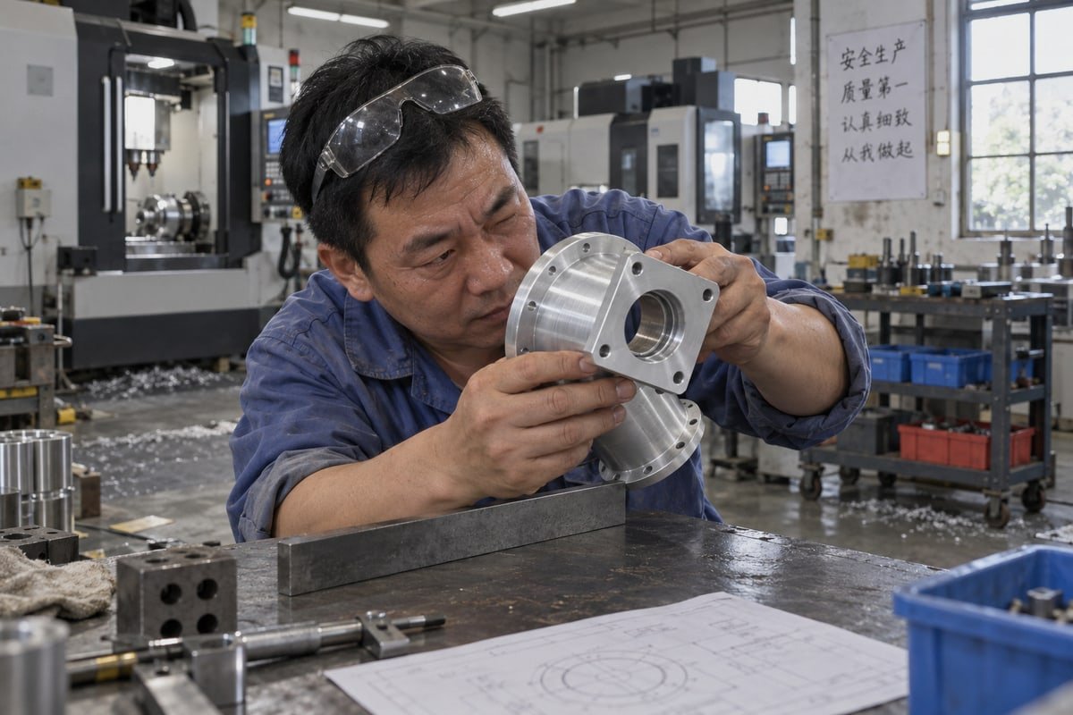
A crooked lens barrel ruins an optical assembly. I have watched buyers lose months over this, which is why our Dongguan shop treats CNC machining for optical equipment components differently.
To source CNC machining for optical equipment components, define datums around the optical axis, specify coaxiality, parallelism, perpendicularity, and flatness, choose thermally stable materials like 6061-T6 aluminum, require CMM inspection reports, and qualify ISO 9001 suppliers who provide DFM feedback before quoting.
Optical sourcing is not about finding a machinist. It is about controlling alignment, surface quality, inspection, and documentation from RFQ to delivery. This guide walks through each step. I will share what works, what fails, and what to demand from any supplier.
How do I choose a CNC machining supplier for precision optical equipment components?
A procurement manager from Munich once told me he had rejected three CNC quotes before finding us. All three shops had missed the datum note referencing the optical axis.
Choose a supplier with proven optical-industry experience, ISO 9001 certification, 5-axis machining capability, in-house CMM metrology, NDA-first file handling, and fast DFM feedback. Verify they machine to 0.005–0.01 mm tolerances and can show first-article inspection reports from similar optomechanical projects.
Most CNC shops can cut metal. Far fewer can hold the alignment that precision optomechanical assemblies demand. The difference shows up in three places: how a shop reads your drawing, how it fixtures the part, and how it proves the result. When we receive drawings for lens barrels, optical housings 1eller laser system components 2, our engineers check the datum scheme before we quote anything. If the datums do not reference the optical axis correctly, we flag it. A supplier that quotes a file without questions is a warning sign, not a convenience.
What Separates an Optical-Capable Shop from a General Shop
Multi-axis capability matters more here than in most industries. 5-axis CNC milling lets us machine a monolithic optical housing in one setup. That eliminates the stack-up errors caused by re-fixturing between operations. Every manual re-fixture adds alignment risk you cannot inspect away later.
| Evaluation Criterion | What to Verify | Red Flag |
|---|---|---|
| Certification | ISO 9001 certification (AS9100 for aerospace optics) | No documented quality system |
| Machining capability | 3/4/5-axis milling, tolerances of 0.005–0.01 mm | Vague claims with no sample reports |
| Metrology | In-house CMM, FAI reports, roughness testing | Calipers-only inspection |
| Engineering support | DFM feedback within 24–48 hours | Quotes with zero questions asked |
| Confidentiality | NDA-first workflow, secure file handling | Reluctance to sign an NDA |
Some buyers ask me whether a single-source shop beats a specialist. My honest answer: single-source reduces coordination risk for most housings, brackets, and mounts. But for exotic geometry or unusual metrology, a specialist may still earn its premium. Ask each vendor which category your part falls into, and judge their answer.
What tolerances and materials should I specify when sourcing CNC machined optical parts?
Twenty years of machining lens barrels taught our team one lesson: the core of optical parts is coaxiality, parallelism, perpendicularity, and flatness. Everything else follows from those four controls.
Specify coaxiality, parallelism, perpendicularity, and flatness on all surfaces that locate optics, holding micron-level tolerances only on critical bores and fits. Choose 6061-T6 aluminum for housings, stainless steel for wear surfaces, and PEEK for insulating parts, and define surface roughness and anodizing requirements clearly.

Here is a buyer objection I hear often: "Shouldn't I just tighten every tolerance to be safe?" No. Blanket ultra-tight tolerances raise cost sharply and improve nothing if the datum strategy is weak. The counterpoint is real, though. Bores that seat lenses, fits that locate sensors, and adjustment features genuinely need micron-level tolerances. The skill is knowing which surfaces earn tight control and which do not. That is exactly where Geometric Dimensioning and Tolerancing 3 (GD&T) beats plain linear dimensions. GD&T ties each control to a functional datum, so the machinist and the inspector both understand what the optical path actually needs.
The Four Geometric Controls That Matter Most
| Geometric Control | Where It Applies | Why It Matters Optically |
|---|---|---|
| Coaxiality | Lens bores, barrel steps, threaded retainers | Keeps optical elements centered on the axis |
| Parallelism | Mounting faces, sensor seats | Prevents tilt between optical elements |
| Perpendicularity | Flanges relative to the bore axis | Controls pointing error at assembly |
| Flatness | Mating and reference surfaces | Ensures repeatable seating without distortion |
Material and Finish Selection
Material thermal stability decides whether alignment survives temperature swings. That is why 6061-T6 dominates optical housings and heat sinks. For high-performance polymers, ask about cryogenic machining techniques, which achieve superior finishes without thermal warping.
| Materiale | Typical Optical Use | Key Property |
|---|---|---|
| 6061-T6 aluminum | Housings, barrels, heat sinks | Stable, light, anodizes well |
| 303/316 stainless steel | Wear surfaces, adjustment screws | Hardness, corrosion resistance |
| Brass/copper | Thermal paths, RF shields | Conductivity |
| PEEK, POM | Insulating spacers, guides | Low outgassing, dimensional stability |
One more detail buyers miss: anodizing and surface finishing must be planned before machining, not after. Matte black hard-coat anodizing controls stray light, but coating thickness changes fits. We mask critical bores or machine them after coating, and we specify surface roughness 4 (Ra) on functional faces. State your finish and masking areas in the RFQ.
How can I verify quality and inspection standards before ordering optical equipment components?
Our CMM room in Dongguan runs almost around the clock during optical projects. I once watched a single housing get probed at forty points before we released the batch.
Verify quality by requiring first-article inspection reports, CMM measurement of all critical dimensions, material certificates, surface roughness reports, and photos of protective packaging. Confirm the supplier holds ISO 9001 certification and ask for sample inspection reports from previous optical equipment component projects before placing an order.

Trust is built with documents, not promises. Before you send a purchase order, ask the supplier to show you what their inspection paperwork actually looks like. A shop that hesitates here will hesitate again when your parts arrive out of spec. On optical programs, critical dimensions are often verified 100% by CMM rather than sampled. That is a real cost, and a serious vendor will price it openly instead of skipping it silently.
The Document Package You Should Demand
| Document | What It Proves | When to Receive It |
|---|---|---|
| First-article inspection (FAI) report | The process produces conforming parts | Before batch release |
| CMM dimensional report | Critical dimensions measured on calibrated equipment | With every shipment |
| Material certificate | Correct alloy and grade, e.g., genuine 6061-T6 | With the quote confirmation |
| Surface roughness (Ra) report | Functional faces meet finish spec | With FAI and batches |
| Outgoing inspection record | Final check before packing | With every shipment |
Two newer expectations deserve mention. First, on-machine probing verifies dimensions in real time before the part leaves the fixture, which catches drift early. Ask whether the shop uses it. Second, digital thread integration means as-built metrology data ships alongside the physical parts, so your optical team can model the real assembly, not the nominal one. Finally, do not ignore cleanliness. Burrs and particulate contamination kill optical assemblies. We ultrasonic-clean parts and use protective, cleanroom-compatible packaging so a perfect part does not arrive scratched. Ask your vendor to photograph packaging before shipment. It takes them two minutes and saves you weeks.
What lead times and production options should I expect when sourcing optical CNC parts from China?
Speed versus process discipline is the trade-off I weigh on every optical order. We can ship prototypes in five days, but production release always deserves a slower, documented ramp.
Expect quotes within 12–48 hours from complete drawing packages, prototypes in 5–10 days, low-volume batches in 2–3 weeks, and mass production in 3–5 weeks from China. Choose suppliers offering rapid prototyping, low-volume manufacturing, and mass production under one roof to keep process assumptions consistent.

Speed starts with your RFQ, not the factory floor. A complete package gets quoted in 12–48 hours. An incomplete one triggers days of email ping-pong. Send the 2D drawing with revision number, the 3D STEP or IGES model, material grade, quantity for both prototype and repeat orders, finish and masking areas, critical fits, inspection requirements, and your delivery target. Add an NDA if the design is sensitive. When buyers give us all of this, our fastest optical prototypes have shipped in five days.
Typical Timeline by Production Stage
| Stage | Typical Quantity | Lead Time | Key Focus |
|---|---|---|---|
| Rapid prototype | 1–10 pcs | 5–10 days | Design validation, FAI |
| Pilot / low volume | 10–500 pcs | 2–3 weeks | Process stability, fixturing |
| Mass production | 500+ pcs | 3–5 weeks | Repeatability, batch QC |
Now the objection worth taking seriously: "A shop that is great at prototypes will handle my production run too, right?" Not automatically. Prototype-friendly vendors optimize for speed and flexibility. Production demands fixed fixturing, statistical dimension control, and consistent anodizing batches. This is exactly why prototype to production scaling should be a stated capability, not an assumption. Ask how the vendor locks the process between the first article and the thousandth part. At our factory, the same fixtures, programs, and inspection plan carry from pilot run to volume, and every batch ships with inspection records. That continuity is what keeps dimension drift, burrs, and hole-position deviation out of your assembly line.
Konklusion
Sourcing CNC machining for optical equipment components succeeds when you control four things: geometric alignment, material stability, documented inspection, and consistent scaling. The best supplier proves all four, every batch.
Remember the four controls that anchor everything: coaxiality, parallelism, perpendicularity, and flatness. Specify them on the surfaces that locate your optics, and relax everything else. Demand FAI reports, CMM data, and material certificates before you commit. Send complete RFQ packages to earn fast, accurate quotes. And pick a partner who treats your prototype as the first article of production, not a one-off favor. The cheapest or fastest quote rarely wins optical programs. The supplier who can consistently prove alignment, finish, and dimensional control with real documentation is the one who keeps your optical system, and your project schedule, intact. If you have drawings ready, our team is happy to review them and return DFM feedback before you spend a single dollar.
Footnotes
1. Provides context on the structural components used to support optical systems. ↩︎
2. IEEE is a leading authority on laser technology and electronic components. ↩︎
3. ASME provides the industry-standard definitions for GD&T in mechanical engineering. ↩︎
4. ISO defines the international standards for surface texture and roughness measurement. ↩︎

 Dansk
Dansk  English
  Italiano
  Français
  日本語
日本語  Deutsch (Sie)
  Español
  Русский
  العربية
  Български
  Čeština
  Suomi
Suomi  עִבְרִית
  हिन्दी
  Nederlands
  Português
  Română
  Slovenčina
  Svenska
  ไทย
ไทย  Tiếng Việt
  Türkçe
  Slovenščina