
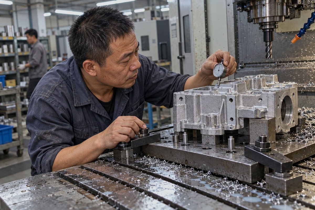
Scrapped parts rarely begin at the cutter. On our Dongguan shop floor, most dimensional drift traces back to weak CNC fixture design. This guide shows how we prevent it.
CNC fixture design basics center on locating a part from defined datums, constraining all six degrees of freedom with the 3-2-1 principle, supporting it near cutting forces, clamping toward locators without distortion, keeping tool and chip access clear, and validating repeatable seating before production.
That is the short answer. The rest of this article breaks it into four practical questions. I will cover fixture type, fixture material, tolerance control, and the mistakes we see most often on complex parts.
How Do I Choose the Right Type of CNC Fixture for My Part?
A German automation buyer once asked us to quote a dedicated hydraulic fixture 1 for a fifty-piece order. We talked him into soft jaws instead, and he saved real tooling money.
Choose a CNC fixture type by matching production volume, part geometry, and tolerance to the holding method: vises or soft jaws for prototypes, modular fixtures for low to medium volume, and dedicated hydraulic, pneumatic, or palletized fixtures for high-volume, repeatable, automated production.
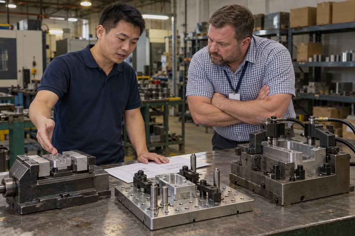
Fixture selection is a cost decision as much as an engineering one. Before I pick a type, I look at three things: how many parts, how often the part changes, and how tight the drawing is. The table below is the same comparison our engineers use when we give DFM feedback on a new quote.
| Fixture type | Best fit | Strengths | Trade-offs |
|---|---|---|---|
| Vise / soft jaws | Prototypes, 1–50 pieces | Fast setup, low cost, jaws machined to match the part | Limited access for multi-side work |
| Plate fixture | Flat, simple parts | Economical, easy to mount | Weak for tall or thin-wall parts |
| Modular fixtures 2 | Low to medium volume, changing product lines | Reconfigurable standard plates, locators, and clamps | Less optimized, more setup effort per run |
| Universal fixture | Mixed part shapes | Reduces tooling investment | Less specialized support and clearance |
| Angle-plate fixture | Fixed-angle or multi-face machining | Holds parts upright for side features | Longer load path, rigidity must be checked |
| Dedicated fixture | One part family, high volume | Best repeatability, fastest loading | Higher design cost, little reuse |
| Hydraulic / pneumatic | Repetitive, automated production | Consistent clamping force, less operator effort | Plumbing, guarding, maintenance, capital cost |
| Vacuum fixture | Thin, flat, delicate, nonmagnetic parts | Low-profile, broad holding | Not for porous stock or heavy interrupted cuts |
| Tombstone / 5-axis | High part density, multi-sided work | Many parts per cycle | Careful collision and chip planning needed |
Start with the workholding principles, not the catalog
A fixture holds and locates a part. A jig also guides a tool, which the CNC control already does. So every fixture type on that list serves the same workholding principles: locate, support, clamp, give access, clear chips, and load fast. Pick the simplest device that does all six for your part.
Dedicated or modular? The objection I hear most
Buyers often tell me a dedicated fixture is "better quality." Sometimes that is true. For a 5,000-piece aluminum housing with a flared base plate, a dedicated nest with hydraulic clamping systems will beat anything modular on cycle time. But for a 200-piece run that may change next quarter, modular fixtures win on lead time and reuse. The right answer depends on volume and part variety, not on which looks more impressive.
A simple selection rule by volume
- Prototype or low volume: vise, soft jaws, plate fixture, or modular kit.
- Medium volume: modular or semi-dedicated fixture with hardened locating pins.
- High volume: dedicated hydraulic, pneumatic, or palletized fixture with zero-point interfaces.
- Very high mix: flexible modular system with standardized mounting interfaces.
Our ISO 9001:2015 process starts every job with this question, because the fixture choice sets setup time optimization for the whole order.
What Materials Should I Use When Designing a CNC Machining Fixture?
Steel or aluminum is the first fork in the road on every fixture drawing that crosses our engineering desk. We weigh stiffness against handling weight before anything else.
Use steel for fixture bodies that carry heavy cutting loads, aluminum for lightweight modular or quick-change fixtures, hardened tool steel for locating pins and wear pads, and engineering plastics where finished or delicate surfaces need soft contact. Match the material to load, wear, and thermal stability.
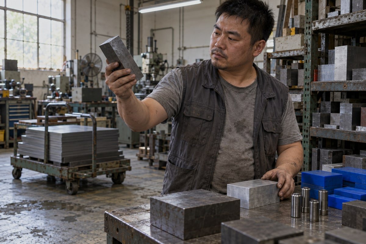
A fixture is a machined part too. We cut fixture bodies on the same 3-axis and 5-axis machines that cut customer parts, so material choice affects our own lead time and cost. Here is how I think about it.
| Matériau | Where we use it | Why | Watch out for |
|---|---|---|---|
| Carbon or alloy steel | Fixture bodies for steel, titanium, and heavy roughing | High stiffness, long wear life | Mass, slower to machine, rust if coolant sits |
| Aluminum (6061 / 7075) | Modular plates, quick-change fixtures, aluminum and plastic parts | Light, fast to machine, easy to modify | Wears faster, deflects more under heavy loads |
| Hardened tool steel | Locating pins, rest buttons, wear pads, clamp tips | Resists repeated contact wear | Needs grinding, higher unit cost |
| Engineering plastics (POM, nylon, PEEK) | Pads touching anodized or polished faces | Protects finished surfaces | Creep under sustained clamping force |
| Granite or stable alloys | Inspection-related or very large tight-tolerance bases | Low thermal movement | Expensive, heavy, special handling |
The "always use steel" objection
Buyers from heavy-equipment companies sometimes insist on all-steel fixtures. For a titanium aerospace bracket under heavy cutting force, I agree. But for an aluminum optical housing 3 with light finishing cuts, an aluminum body with hardened steel contact points gives enough machining stability at a third of the weight. The operator loads it faster and the machine table carries less dead load. Rigidity should come from geometry and short load paths, not only from the densest material.
Design the wear points as replaceable parts
The body rarely wears out. The contact points do. So we press hardened locating pins and rest buttons into aluminum or steel bodies and treat them as consumables. When a pin shows wear, we swap it instead of rebuilding the fixture. This keeps batch production dimensions stable long after the first article.
Do not forget thermal expansion
Aluminum grows about twice as much as steel for the same temperature rise. On a long fixture holding several parts, a warm afternoon or a long cycle with heavy coolant can shift locator positions. For tolerances near 0.01 mm, we either use steel bodies, let the fixture soak to shop temperature, or probe the fixture offset before the run.
How Can I Ensure My Fixture Design Maintains Tight Tolerances During Production?
Last year our inspection team rejected a batch of cylindrical housings over a bore position shift. The cause was not the machine. A single chip sat under one rest button.
Maintain tight tolerances by locating directly from the part's engineering datums, using precision-ground locators and hardened contact points, clamping toward supports rather than across thin sections, controlling chips and thermal growth, probing fixture offsets, and verifying full seating before every cycle.
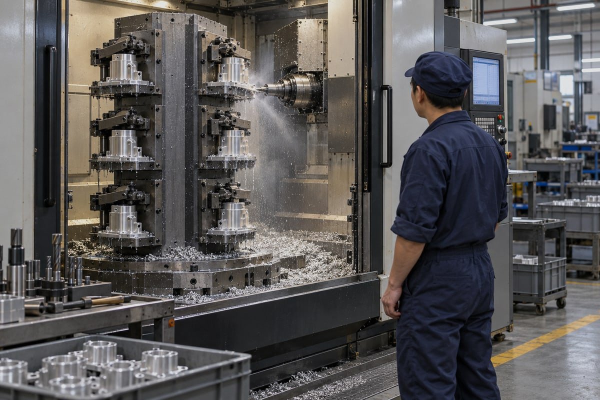
Tight tolerance is not one feature of a fixture. It is the result of many small decisions that either add or remove variation. I will walk through the ones that matter most on our floor.
Control all six degrees of freedom
A rigid body can move six ways: along X, Y, and Z, and rotating about each axis. The 3-2-1 location principle is the standard way to stop all six. Three locators under the part set the primary plane. Two on one side set the secondary plane. One on the adjacent side sets the tertiary plane. Clamps then push the part onto those six points. They never locate the part themselves.
This is a framework, not a formula. A round locating pin controls two directions. A diamond pin is relieved in one direction so two holes with normal positional variation do not fight each other. Cylindrical, thin-wall, or cast parts may need V-blocks, nests, or contoured supports instead.
Accuracy, repeatability, and resolution are different things
- Accuracy: how close the machined feature lands to the drawing.
- Repeatability: how consistently the fixture seats part after part.
- Resolution: the smallest adjustment a locator or stop can make.
A fixture can be accurate on the first article and still fail on piece 300 because repeatability dropped. Worn pins, variable stock, chips under datums, and uneven clamping force are the usual causes.
Know where the stack-up comes from
| Variation source | Typical fix |
|---|---|
| Machine table or pallet location | Keyed or zero-point interfaces, probed offsets |
| Fixture mounting | Dowel pins plus bolts, not bolts alone |
| Locator size and wear | Precision-ground hardened pins, scheduled replacement |
| Part datum variation | Locate from the drawing's datums, not convenient faces |
| Clamping deformation | Clamp toward supports, limit force on thin walls |
| Thermal movement | Steel bodies, temperature soak, in-process probing |
| Chip and coolant contamination | Relief pockets, drainage paths, visible seating faces |
The biggest single improvement is to locate from the same datums the drawing and the inspection report use. Chaining dimensions through secondary faces doubles the stack-up for no gain.
Link the fixture to the machine coordinate system
Once mounted, the machine must know where the fixture sits. We probe datum features 4 and store the result in a work offset such as G54 through G59. That is a control detail, not a design rule, but a fixture that gives the probe clear access makes this step reliable every time.
What Mistakes Should I Avoid When Designing Fixtures for Complex CNC Parts?
Twenty years of machining taught us that the most expensive fixture errors look harmless in CAD. The clamp fits, the model is clean, and the first part still bends.
Avoid clamping on unsupported areas, using clamps as locators, overconstraining the part, blocking cutter or probe access, ignoring tool-holder clearance, letting chips collect under datums, over-forcing thin walls, skipping wear-part replacement, and failing to validate the fixture against the real toolpath and machine envelope.
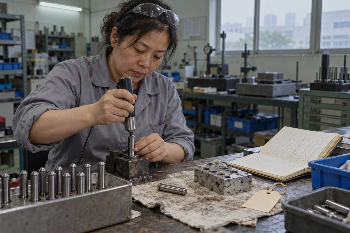
Complex parts punish small fixture errors. A turbocharger housing cut on our 5-axis machines, or a mold base with stepped pockets and guide posts, gives the cutter many angles of attack. Each angle is a chance for a collision or a deflection. Below are the mistakes we correct most often, in the order we check them.
The clamping force objection: is more always safer?
No. This is the misconception I argue against most. A thin-wall aluminum housing clamped hard will measure perfect while clamped and spring out of tolerance when released. The goal is controlled stiffness and force direction. Estimate the cutting load, add friction and a safety margin, then aim the clamp straight at the nearest support. Never treat clamping force as guesswork, and never confuse it with rigidity.
Check tooling clearance against the real tool, not the ideal tool
The cutter is only part of the envelope. The tool holder, the spindle nose, the probe, and the coolant nozzles all need room. We run a CAD interference check 5 with the actual holder model and then a machine simulation of the full toolpath. A fixture that holds the part perfectly but forces a shorter, weaker tool has already lost surface finish and machining stability.
A quick mistake-to-fix map
| Mistake | What it causes | What we do instead |
|---|---|---|
| Clamp on an unsupported wall | Deflection, chatter, out-of-tolerance when released | Add a support directly under the clamp |
| Chips trapped under locators | Part lifts off datum, bore position shifts | Relief pockets, drainage, visible seating faces |
| Clamp handle in the toolpath | Crash or forced tool change | Low-profile or hydraulic clamps, simulation check |
| Symmetric nest on an asymmetric part | Reversed loading, scrapped batch | Orientation key or foolproof pin |
| Fixed pins on cast surfaces | Rocking, poor repeatability | Adjustable or spring-loaded supports with lock |
| No seating confirmation | Silent errors in automated cells | Air-sense, sensor, or visual gap check |
Design for the whole process, not just the cut
A fixture also has to survive loading, unloading, deburring, cleaning, and inspection. If an operator cannot see whether the part is fully seated, the design is incomplete. Newer tools help here: embedded sensors can confirm clamp pressure and seating before the spindle starts, generative design can trim fixture weight without losing stiffness, and specialized approaches like phase-change support media or cryogenic holding exist for very thin or very soft components. They add cost and failure modes, so for low-volume work a simple, validated manual fixture is still often the best economic choice.
Conclusion
Weak fixturing quietly scraps good parts. The fix is simple: define datums, constrain six degrees of freedom, clamp toward supports, keep access clear, and validate before production.
Footnotes
1. Authoritative reference for specialized workholding devices used in high-volume automated production. ↩︎
2. Government resource for manufacturing technology and modular production systems. ↩︎
3. Example of precision-engineered components requiring specific material and stability considerations in aerospace. ↩︎
4. International standard for defining reference points in geometrical product specifications. ↩︎
5. Technical standard for digital representation and verification of machined parts and toolpaths. ↩︎

 Français
 English
 Italiano
 日本語
 Deutsch (Sie)
 Español
 Русский
 العربية
 Български
 Čeština
 Dansk
 Suomi
 עִבְרִית
 हिन्दी
 Nederlands
 Português
 Română
 Slovenčina
 Svenska
 ไทย
 Tiếng Việt
 Türkçe
 Slovenščina