
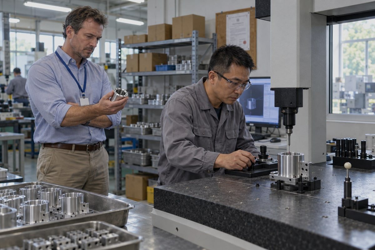
Picking a [CNC machining supplier for optical instruments](https://stcncmachining.com/?p=15520) by price alone is risky. One decentered bore ruins alignment. Our Dongguan team learned this reworking parts other shops had botched.
Choose a CNC machining supplier for optical instruments by verifying micron-level tolerance capability on alignment features, relevant optomechanical experience, suitable materials and stress control, stray-light surface finishes, documented CMM inspection, and a quality management system. Confirm all of it with a first-article order before scaling production.
That is the short answer. The long answer is a risk-management process. You need to know which features decide optical performance, prove the supplier can control them, and validate the process before you commit volume. The four questions below walk through that process in order.
What Precision Tolerances Should I Expect from an Optical Instrument CNC Machining Supplier?
Last year a detector housing passed every length and diameter check on our CMM. Then our final datum check caught it. The bore was not coaxial with the mounting face.
Expect an optical instrument CNC machining supplier to hold micron-level tolerances of ±0.01 mm to ±0.005 mm on alignment features such as lens bores, seating shoulders, and datum faces, with geometric controls for coaxiality, parallelism, perpendicularity, and flatness, while general dimensions keep looser, cost-effective tolerances.

That detector housing taught us something we now say to every new buyer. Dimensional accuracy and optical alignment accuracy 1 are two different things. A supplier who understands only the first one will hurt you on the second.
Dimensional Accuracy Is Not Alignment Accuracy
Optomechanical components do two jobs at once. They carry structural load, and they define where the optical axis sits. So the tolerances that matter are relationships between features, not isolated numbers. A lens cell with a perfect bore diameter still fails if that bore tilts relative to the seating shoulder. The lens decenters, the focus drifts, and the assembly team blames the optics.
| Caraterística | What It Controls in the Instrument | Geometric Control to Specify |
|---|---|---|
| Lens bore | Decentering, optical-axis concentricity | Position, circularity, coaxiality to primary datum |
| Seating shoulder | Lens tilt, focus position | Flatness, perpendicularity to bore axis |
| Mounting face | Angular alignment to adjacent part | Flatness, parallelism to opposite face |
| Mirror pad | Wavefront error, tilt | Flatness, surface roughness Ra |
| Thread or adapter interface | Repeatable assembly | Runout, position |
Why ±0.01 mm Everywhere Costs More and Helps Less
Some buyers assume that tightening every dimension protects optical performance. In our experience it does the opposite. A drawing with ±0.01 mm on every feature creates ambiguity, raises cost, and starts inspection disputes. The better approach is simple. Build the datum structure around the optical axis and the assembly sequence. Then tolerance the optical interfaces tightly and let everything else breathe. A good supplier should be able to read your GD&T scheme and explain how it becomes a machining plan and an inspection plan.
Ask How Tolerances Are Held, Not Just Achieved
On our 3-, 4-, and 5-axis mills we work to 0.01 mm and, on the right features, 0.005 mm. But hitting that once on a prototype is not the same as holding it across a batch. Five-axis machining helps because several bores and faces can share one setup, which removes stack-up error. Still, the machine alone does not guarantee results. Fixturing, clamping deformation, spindle runout, tool wear, and thermal drift decide the outcome. So ask these questions directly:
- How many setups does my part need, and which features finish in one setup?
- Which surface becomes the primary datum, and how is it supported?
- How do you prevent clamping deformation on thin walls?
- How do you monitor tool wear and temperature during a run?
A supplier who answers with machine brands instead of methods is a warning sign.
How Do I Verify a Supplier's Experience with Optical Instrument Components?
A German procurement manager once asked us to mark the three features on his lens barrel drawing that would hurt image quality first. That was a smart question.
Verify a supplier's optical instrument experience by requesting anonymized drawings or inspection reports from similar optomechanical components, asking which features on your drawing are critical to optical performance and how they would be inspected, reviewing CMM inspection reports with actual values, and placing a small pilot order before volume.

His question worked because it forced an engineering answer, not a sales answer. We walked through the bore, the seating shoulder, and the thread runout, and we explained how each would be checked. Any CNC machining supplier for optical instruments should be able to do the same within a day of seeing your drawing. Here is the staged process we recommend to buyers who compare us against other shops.
- Shortlist three to five suppliers who are technically plausible for the part.
- Review their equipment, quality system, material experience, and finishing network.
- Send every supplier the identical RFQ package: STEP model, 2D drawing, material grade 2, finish spec, critical features, quantities, and required documents.
- Compare the proposed manufacturing route and setups, not just the unit price.
- Ask each supplier to name the highest-risk features and explain how they would inspect them.
- Check references or request anonymized examples of lens cells, mirror holders, or detector housings.
- Place a manageable pilot order and compare the supplier's data against your own measurements.
Evidence That Counts More Than a Certificate
Our factory holds ISO 9001:2015 certification 3, and we are proud of it. But we tell buyers plainly that ISO 9001 certification proves a framework, not a tolerance. It shows the supplier has document control, calibration records, and a corrective-action process. It does not show that they can hold a 0.005 mm coaxiality on a deep bore. For that you need part-specific evidence: a CMM inspection report 4 with measured values, not pass/fail ticks, plus a first-article report you can verify yourself.
Use DFM Feedback as a Test
Design for Manufacturing DFM feedback is one of the fastest ways to judge experience. When a buyer uploads drawings to us, our engineers look for thin walls that may deflect, deep pockets with poor tool access, sharp internal corners, unclear datums, and tolerances that add cost without adding function. Then we propose alternatives and explain the trade-offs. Generic reassurance like "no problem, we can do it" is the opposite of DFM. If a supplier quotes from the CAD model and never mentions the 2D drawing, they have not read your tolerances.
Red Flags We Would Watch For
- The supplier cannot identify critical datums or optical interfaces.
- They promise every tolerance before reviewing the drawing.
- They offer an unusually short lead time without stating assumptions.
- They resist a prototype or first-article order.
- They hide subcontracted finishing.
What Materials and Surface Finishes Matter Most for My Optical Instrument Parts?
Weighing 6061-T6 against stainless steel for a lens cell is a trade-off we run constantly: weight and machinability on one side, stiffness and corrosion resistance on the other.
The materials that matter most for optical instrument parts are 6061-T6 and 7075 aluminum, stainless steel, titanium, Invar 36, and PEEK, chosen for thermal expansion and stability. Critical finishes include matte black anodizing for stray-light suppression, hard anodizing, passivation, and electroless nickel, with coating thickness planned into tolerances.

The right material is the one that stays still. That sounds obvious, but material thermal expansion, residual stress, and finishing all push a part away from its drawing after machining. Our stance on optical work rests on three things: ultra-precision machining, low deformation, and high surface quality. Material choice sits under all three.
Choosing for Stability, Not Just Strength
| Material | Why Optical Buyers Choose It | Machining and Stability Notes |
|---|---|---|
| 6061-T6 aluminum | Light housings, mounts, precision lens housings | Easy to machine; anodizes well; use stress-relieved stock 5 |
| 7075 aluminum | Higher strength frames and stages | Stronger but more prone to warping; plan rough-and-rest cycles |
| Stainless steel (303/304/316) | Wear surfaces, corrosion resistance, structural parts | Heavier; passivation needed; slower to machine |
| Titânio | Weight-sensitive, high-strength parts | Low expansion relative to aluminum; demanding on tooling |
| Invar 36 | Focus stability across temperature changes | Very low expansion; gummy to machine; needs experienced shop |
| Copper / OFHC | Thermal management near detectors | Soft; burr control matters |
| PEEK and engineering plastics | Insulation, low-mass components | Low outgassing grades available; avoid heat buildup during cutting |
Low Deformation Starts Before the First Cut
Residual stress is the quiet killer of optical parts. A housing can measure perfectly on the machine and warp a week later after anodizing releases stress. In our workshop we ask for stress-relieved stock, rough machine, let the part rest, then finish in a controlled sequence. We also inspect after finishing, not only before. Ask your supplier for the material grade, temper, mill certificate, and batch traceability. Buyers worry about 6061 being swapped for ordinary aluminum or 304 for 316. A mill certificate tied to a lot number closes that gap.
Surface Quality Is an Optical Spec, Not a Cosmetic One
Surface roughness Ra on a mirror pad or seating shoulder affects how a lens seats and how light scatters. Inside a barrel, a matte black anodizing or bead-blasted black finish suppresses stray light. For vacuum or space-based instruments, cleaning must be hydrocarbon-free and outgassing must be controlled. For optical polymers, some shops use cryogenic machining to get brittle-mode cutting and avoid smeared surfaces.
Some buyers prefer a supplier who does all finishing in-house. We understand the appeal, but a specialist anodizer often delivers a more uniform coating inside deep cavities. What matters is who owns the chain. We control the specification, the masking of threads and bores, the coating thickness in the dimensional plan, and the post-finish inspection. Outsourcing is acceptable when the prime supplier owns those four things.
Cleanliness and Packaging Close the Loop
A perfect part that arrives with coolant residue or a scratched datum face is a failed part. We ultrasonic clean, cap bores and threads, wrap parts individually, and use shock-resistant packaging for overseas shipments to Europe and North America.
How Can I Ensure Consistent Quality When Scaling Production for My Optical Instrument Project?
Our hardest lesson came from a part that passed first article beautifully and then drifted in batch three. Tool wear, not the program, was the culprit.
Ensure consistent quality when scaling optical instrument production by treating the first article as process validation, locking the manufacturing route and fixtures, requiring in-process probing and per-batch CMM inspection reports, enforcing material-lot traceability under an ISO 9001 quality management system, and agreeing on change-notification and acceptance criteria in writing.

That drift episode changed how we run repeat orders. We now probe critical bores in-process and set tool-change intervals from measured wear, not from guesswork. The point for buyers is this: sample quality and batch quality are different capabilities. A CNC machining supplier for optical instruments must prove both.
What Changes Between Prototype and Production
| Control Area | Prototype Stage | Production Stage |
|---|---|---|
| First article | Dimensional check against drawing | Full process validation with CMM data on every critical feature |
| Fixturing | Flexible, may be modular | Dedicated fixtures locked to a documented setup |
| Inspection | Sample measured, lighter documentation | In-process probing plus per-batch CMM inspection report |
| Traceability | Material cert on request | Lot and serial identification tied to mill certificates |
| Change control | Informal | Written revision control and change notification |
| Packaging | Basic protection | Defined separation, labeling, caps, and corrosion protection |
Treat the First Article as a Process Audit
A first article is not paperwork. It is your chance to compare the supplier's inspection data with your own independent measurements. We provide a first article inspection report, a CMM inspection report with actual values, and material certificates. If a feature is near the edge of tolerance on the first article, it will fall outside during production. Fix the process then, not later.
Prototype Speed Versus Production Stability
Here is a common buyer objection. A fast prototype shop may not have the capacity or documentation for repeat production, and a big production shop may be slow during development. Our answer is to support both under one roof. We quote lead times as short as 5 days on prototypes, and we carry the same drawing revision, fixtures, and inspection plan into low-volume and mass production. If you must split prototype and production between two partners, define the handoff deliberately: who owns the fixtures, the program, and the inspection method.
Total Cost Beats Unit Price
Price-first sourcing can work for a simple bracket with broad tolerances. It fails for alignment-critical parts. A low unit price that excludes inspection, finishing, special packaging, or engineering time becomes expensive after sorting, rework, and expedited replacement. We put all assumptions in writing before an order, and we back shipped parts with a 30-day warranty. The trend we see from buyers in Germany, the United States, and Japan is clear: they expect digital inspection data, revision control, and sometimes as-machined point-cloud data for as-built ray-tracing. Match the rigor to the risk of the part.
Conclusion
Cheap quotes hide alignment risk. Demand proof: critical datums, stress control, finish planning, CMM data, a validated first article. Send us your drawing and we will mark the risks first.
Footnotes
1. Homepage of the international society for optics and photonics, relevant to optical instrument accuracy. ↩︎
2. Official site for ASTM International, which defines material grades and testing standards for manufacturing. ↩︎
3. Official ISO page for the 9001:2015 quality management standard mentioned in the text. ↩︎
4. Overview of coordinate-measuring machines used for micron-level inspection of optomechanical components. ↩︎
5. Technical explanation of the stress-relieving process used to ensure material stability in precision parts. ↩︎

 Português
 English
 Italiano
 Français
 日本語
 Deutsch (Sie)
 Español
 Русский
 العربية
 Български
 Čeština
 Dansk
 Suomi
 עִבְרִית
 हिन्दी
 Nederlands
 Română
 Slovenčina
 Svenska
 ไทย
 Tiếng Việt
 Türkçe
 Slovenščina