
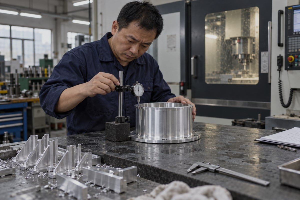
A thin-wall housing can measure perfectly on the machine, then warp once unclamped. On our Dongguan production line, that painful lesson shaped how we prevent deformation in thin-wall CNC parts.
Preventing deformation in thin-wall CNC parts means controlling it within tolerance, not eliminating it. Use stress-relieved stock, distributed low-force workholding, short rigid tools, small radial engagement, symmetrical staged material removal, temporary ribs, and inspection after unclamping and cooling.
Let me be honest up front. Absolute zero deformation is very hard to reach. Our real goal is different. We want the deformation to stay inside the drawing tolerance, so the part works, assembles smoothly, and repeats batch after batch. The sections below walk through the causes, the fixturing choices, the material and sequence decisions, and how to judge a supplier.
What Causes Deformation in My Thin-Wall CNC Parts During Machining?
Last year our QC team rejected a batch of aluminum sensor housings. Every wall measured fine while clamped. After release, flatness drifted past the drawing limit.
Thin-wall CNC parts deform because low stiffness makes them vulnerable to radial cutting forces, excessive clamping force, tool deflection, chatter, cutting heat, and residual stress released from the stock. Deformation grows when forces rise and falls when support, stiffness, and force distribution improve.
The first thing I tell new engineers is that "thin wall" has no fixed number. A 2 mm wall on a short, ribbed bracket may be stiff. A 2 mm wall on a tall, open housing may flex like a spring. What matters is the wall thickness ratio, meaning height divided by thickness, plus the unsupported length, the material, the curvature, and whether we mill or turn the part. The same wall can also change behavior during the job. It may be stable while surrounded by stock, then unstable once a pocket opens, then distorted again when a rib is removed.
The Six Ways a Thin Wall Fails
| Failure mode | What happens | Typical trigger |
|---|---|---|
| Elastic bending | Wall springs away from the tool, then returns | High radial engagement, dull edge |
| Clamping deformation | Part is distorted before cutting starts | Concentrated or excessive clamping force |
| Chatter and vibration | Wavy surface, poor size control | Long tool overhang, unstable engagement |
| Thermal distortion | Size changes after cooling | Poor heat dissipation, uneven coolant |
| Residual stress release | Part warps as stock is removed | Rolled plate, castings, forgings |
| Drift after unclamping | Part relaxes to a new shape | Fixture was holding it in a false position |
Cutting Forces and Tool Deflection
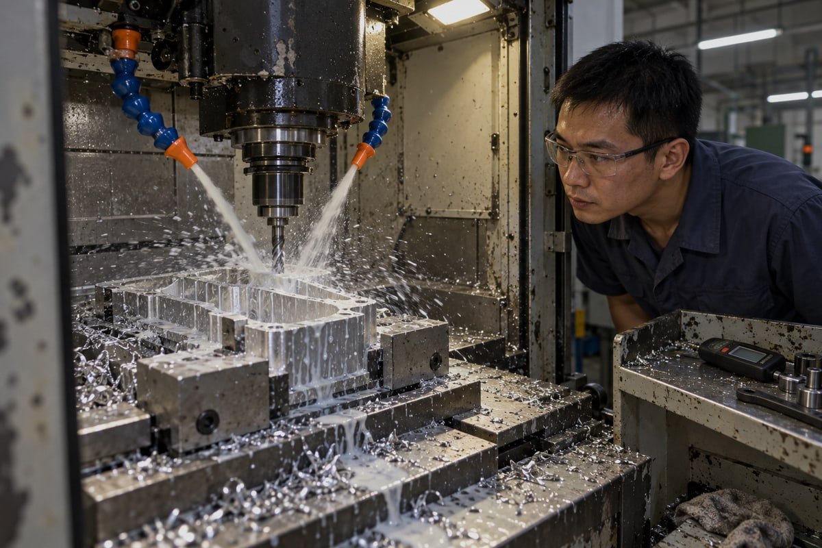
Radial force is the main enemy. It pushes straight against the flexible wall. Deep cuts, heavy feed, blunt tools, and sudden direction changes all create force spikes. Keeping radial engagement around 10–20% of tool diameter is a common starting point for suitable milling work, but the right value depends on the tool, material, and machine. Tool deflection adds to the problem. A long end mill bends a great deal more as its unsupported length grows. We try to keep overhang near or below a 3:1 ratio, and we reach for a larger-diameter tool with a shorter gauge length whenever the geometry allows.
Residual Stress and Heat
Rolled 6061 plate often carries uneven internal stress. Remove material from one side, and the balance breaks. The part warps even when cutting forces are low. Heat works in a similar sneaky way. Aluminum expands during cutting, so the wall measures correctly while warm and wrong after it cools. Coolant helps, but coolant alone cannot fix an unstable toolpath or a poor fixture.
How Can I Choose the Right Fixturing Method to Keep My Thin-Wall Parts Stable?
Vacuum plates or soft jaws? We weigh this choice on almost every flat thin-wall plate quote, because the wrong fixture costs more than any feed-rate error.
Choose workholding fixtures that spread clamping force over the largest practical contact area, clamp only robust regions, support the wall near the cutting zone, and apply minimum force. Vacuum plates, form-fit soft jaws, mandrels, and temporary ribs each suit different thin-wall geometries.
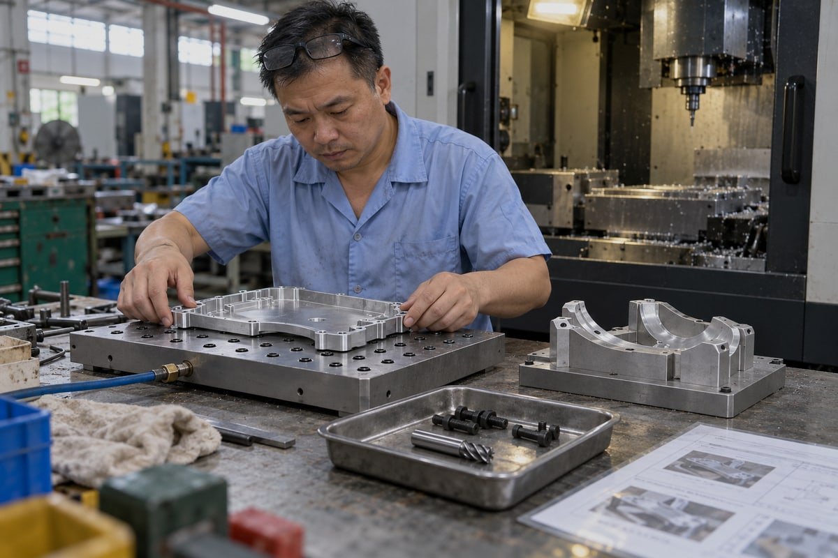
Fixturing is a design decision, not a setup detail. Our process engineers plan the fixture at the DFM stage, before the program is written. The rule is simple. Match the support direction to the cutting force direction, and never let a clamp push on a wall that will be thin at the end of the job.
Comparing Common Workholding Fixtures for Thin Walls
| Method | Best for | Strength | Watch out for |
|---|---|---|---|
| Vacuum fixture | Broad, flat plates | Even pressure, no clamp marks | Weak against lateral forces; needs flat sealing surface |
| Form-fit soft jaws | Contoured housings | Large contact area, low local stress | Can allow vibration if poorly supported |
| Expanding mandrel / axial sleeve | Turned cylindrical walls | Loads the strong axial direction | Must match bore size closely |
| Wax or foam cavity filling | Hollow, deep sections | Adds temporary rigidity and vibration dampening | Cleaning and thermal limits |
| Temporary ribs and tabs | Any flexible geometry | Keeps stiffness through roughing | Extra material and removal cost |
Buyers often push back on vacuum fixtures. The objection is fair. A vacuum plate distributes force well, but it may not resist side loads during heavy roughing, and a lost seal means a scrapped part. Our answer is to combine methods. We rough on robust datum pads with mechanical clamps 1, then finish on vacuum once the heavy forces are gone. Another objection concerns soft jaws. Yes, they can let a part ring if the jaw walls are thin. So we keep the jaw stock thick and add support pads close to the cut.
Release, Reclamp, and Verify
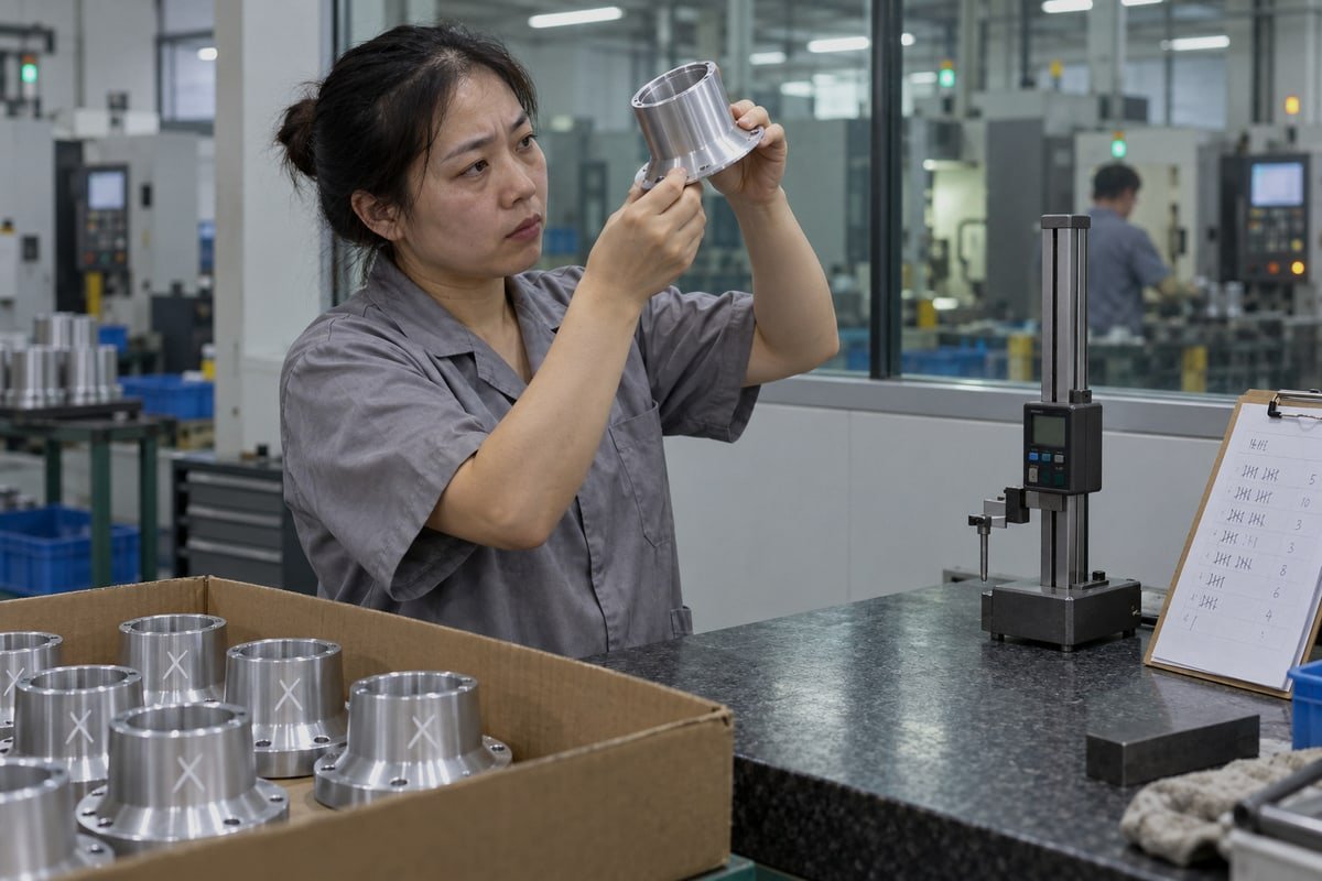
One habit has saved us many parts. After roughing, we loosen the clamps, let the part spring back, then reclamp at minimum force before finishing. This releases elastic strain the fixture was hiding. We also probe the part after clamping. If the fixture itself has bent the wall, the probe shows it before the first finishing pass. For turned thin-wall housings like the flared-base cylinder in our catalog, we prefer end-face clamping over three-jaw radial gripping. Radial pressure ovalizes a thin ring. Axial pressure runs along the stronger direction. Deformation in thin-wall CNC parts often starts in the fixture, so this is where we spend the most planning time.
Which Materials and Machining Sequences Help Me Reduce Warping in Thin-Wall Components?
A German buyer once asked why we quoted stress relief annealing on a 6061 plate part. His drawing had thin walls and flatness the raw plate could never hold.
Stress-relieved aluminum, stabilized stock, and sharp positive-rake carbide tools reduce warping. Sequence machining by changing stiffness: rough with uniform stock, keep temporary ribs, recheck datums, semi-finish, alternate sides symmetrically, finish thin walls last with small radial engagement, then inspect after cooling.
Material choice sets the baseline. Aluminum cuts easily but flexes and conducts heat fast. Stainless steel and titanium resist bending more, but they generate higher cutting loads and trap heat at the edge. Engineering plastics like POM or PEEK can creep under clamping force or temperature. Before any demanding thin-wall job, we confirm the material certificate and condition, let the stock reach shop temperature, and ask whether stress relief annealing, aging, or vibratory stress relief is worth the lead time. For many plate parts, it is.
Material Behavior in Thin-Wall Work
| Materiál | Stiffness | Heat behavior | Main risk | Our usual preparation |
|---|---|---|---|---|
| 6061 / 7075 aluminum | Low | High conductivity | Residual stress from rolling | Stress-relieved plate, rough near-net first |
| 304 / 316 stainless | Medium | Low conductivity | Work hardening, heat at the edge | Sharp coated carbide, flood coolant |
| Titán | Medium | Very low conductivity | Thermal distortion, tool wear | Conservative engagement, strong heat dissipation |
| POM / PEEK | Very low | Expands with temperature | Clamp marks, creep | Minimal clamping force, light passes |
The Sequence We Follow
- Establish reliable datums on a rigid area.
- Rough all major pockets and cavities, leaving uniform stock on every thin wall.
- Keep temporary ribs, bridges, or process bosses in place.
- Release, reclamp, and recheck datums after heavy removal.
- Semi-finish critical surfaces while the part still has stiffness.
- Alternate sides or zones so residual stress releases evenly.
- Finish the least-supported walls last with low-force passes.
- Remove temporary supports near the end, in a planned order.
- Take a final light cleanup pass if needed.
- Inspect after unclamping and thermal stabilization.
The key idea is to machine according to the part's changing stiffness, not the feature order in the CAD tree.
Tools, Toolpaths, and Parameters
High-speed machining with low radial engagement 2 is our default for aluminum walls. Trochoidal or adaptive paths keep engagement constant, which matters more than simply lowering every number. Sudden corner entries create force peaks even when averages look safe. We use variable-helix end mills 3 for vibration dampening on tall walls. Climb milling usually gives a cleaner wall and lower push-off on our rigid machines, but conventional milling can be the better choice on a machine with backlash, so we test rather than assume. One warning: an extremely light finishing cut is not automatically safer. If the chip load drops too far, the edge rubs instead of shearing, heat rises, and the wall moves.
For thin-wall turning, we rough in several stages, finish in a separate setup, keep the finishing insert sharp, and limit the wiper edge to roughly 0.2–0.3 mm so it does not drag along the wall. We also measure roundness and wall thickness after the part leaves the chuck, never only while it is held.
How Do I Find a CNC Supplier Who Can Consistently Deliver Precise, Deformation-Free Thin-Wall Parts?
The hardest lesson in twenty years of machining was this: a perfect first sample proves nothing about thin walls. Batch stability is what buyers actually pay for.
Find a supplier who defines deformation targets within tolerance, offers DFM feedback on walls and fixtures, uses stress-relieved stock, documents fixture and process settings, inspects after unclamping and cooling, holds ISO 9001:2015 certification, and proves repeatability with first-article and batch inspection reports.
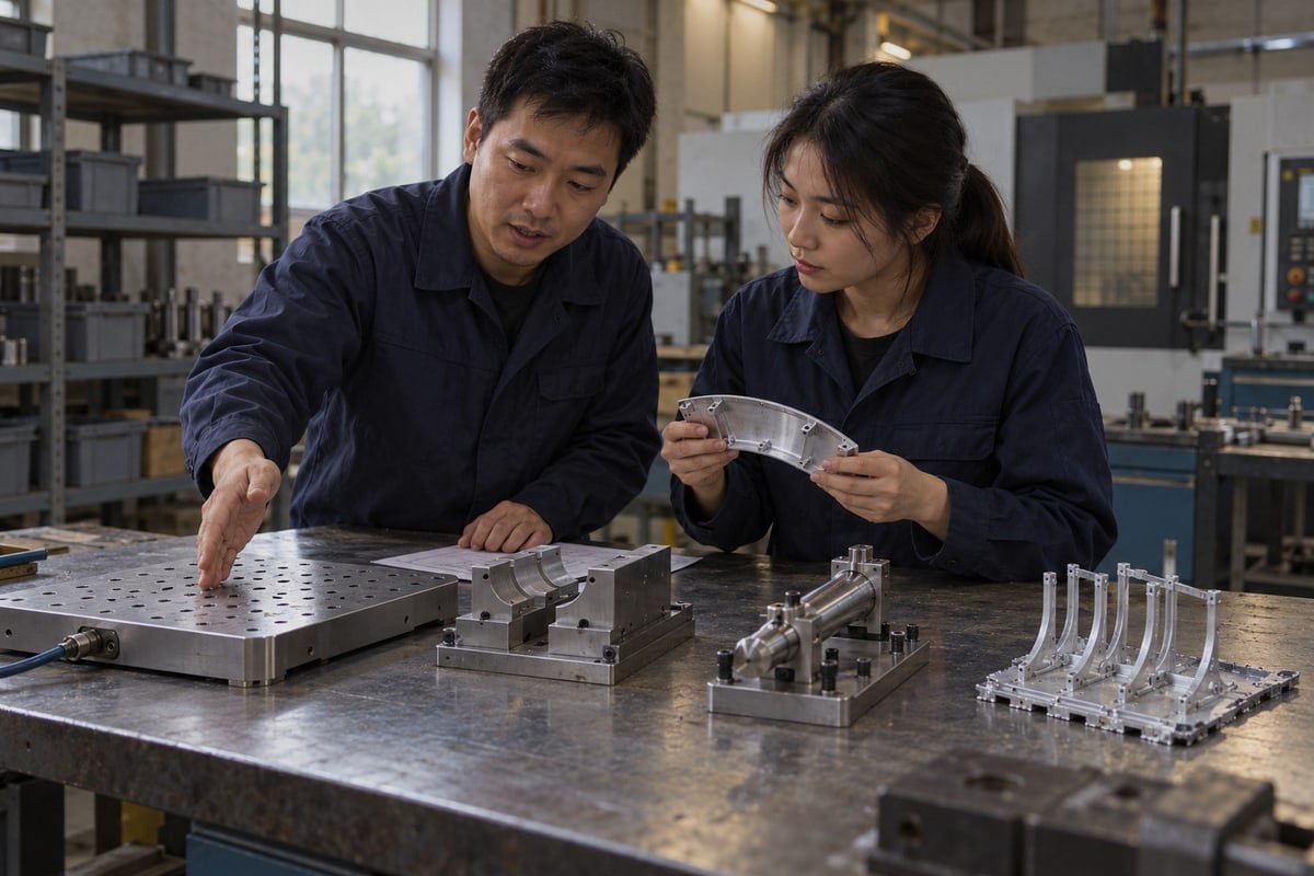
Here is the uncomfortable truth I share with procurement managers. Any shop can make one thin-wall part look good. The sample gets extra attention, a slow program, and a careful operator. The failure shows up at piece fifty, when tool wear rises, coolant warms up, and someone tightens a clamp a little harder. So the questions you ask should target the process, not the sample.
Questions That Separate Capable Shops From Hopeful Ones
| Question to ask | Weak answer | Strong answer |
|---|---|---|
| How will you fixture this wall? | "Standard vise." | A sketch showing contact area, clamp points, and support near the cut |
| Is the stock stress relieved? | "Standard plate." | Material certificate plus stress relief plan for critical parts |
| When do you measure the thin wall? | "At final inspection." | After roughing, after unclamping, and after cooling |
| How do you keep batch stability? | "Same program." | Recorded clamp torque, tool-life limits, coolant checks, in-process probing |
| What if the part is out of tolerance? | Silence | Clear rework, remake, or warranty response |
What a Realistic Promise Sounds Like
Be careful with suppliers who promise zero deformation. Nobody can honestly promise that on a tall, thin wall. What we promise instead is a defined deformation budget inside the drawing tolerance, with proof. On our 5-axis mills we hold 0.01–0.005 mm on suitable features, but we tell customers when a wall thickness ratio makes a tolerance unrealistic, and we propose a rib, a radius, or a thicker datum pad in the DFM review. Five-axis access lets us use shorter tools and lower tool deflection, though it adds programming effort, so we only use it when it pays off.
Inspection is feedback, not just acceptance. We probe datums after roughing, compare measurements before and after unclamping, and use CMM or scanning for complex profiles. FEA-based deformation prediction, toolpath pre-compensation, and adaptive offset control are useful on high-value parts, but they complement sound fixturing and sequencing. They do not replace them. Ask for first-article reports, material certificates 4, and outgoing inspection records, because these documents feed your own acceptance process. Finally, ask about packaging. A thin-wall housing that survived machining can still be deformed in a loose carton on a three-week sea route. Our ISO 9001:2015 system, DFM feedback, lead times as short as 5 days, and 30-day warranty exist because overseas buyers need those answers before they trust a shop with deformation in thin-wall CNC parts.
Záver
Thin walls will always move a little. The win is keeping that movement inside tolerance through design, fixturing, tooling, sequencing, and inspection. Send us your drawing for DFM feedback.
Footnotes
1. Reference for mechanical clamps used to secure workpieces during the initial stages of CNC machining. ↩︎
2. NIST research provides technical benchmarks for low radial engagement in high-precision CNC machining. ↩︎
3. Technical overview of variable-helix end mills used to suppress vibration in thin-wall machining. ↩︎
4. ISO standards govern the quality management systems required for authentic material certificates in manufacturing. ↩︎

 Slovenčina
 English
 Italiano
 Français
 日本語
 Deutsch (Sie)
 Español
 Русский
 العربية
 Български
 Čeština
 Dansk
 Suomi
 עִבְרִית
 हिन्दी
 Nederlands
 Português
 Română
 Svenska
 ไทย
 Tiếng Việt
 Türkçe
 Slovenščina