

[Poor CNC machining accuracy](https://stcncmachining.com/?p=15385) rarely announces itself GD&T standards 1. A part passes visual checks, then jams at assembly weeks later. On our Dongguan floor, we treat accuracy as a process-control problem.
To improve CNC machining accuracy, measure existing errors first, then correct machine alignment and thermal drift, stabilize workholding and tool runout, separate roughing from finishing, optimize toolpaths, and add probing or statistical process control. Consistent tolerances come from controlling variation at every stage, not from buying a costlier machine.
The rest of this article follows the order we use in our own shop material certificates 2. First, we find the error. Then we fix the machine, the heat, the setup, and the cut. Finally, we lock the result in with inspection. If you buy CNC parts rather than make them, the same logic tells you what to ask a supplier.
How do I identify the root causes of CNC machining inaccuracy in my parts?
A batch of thin-walled aluminum housings once drifted out of tolerance mid-shift in our shop. The first ten parts measured fine. Spindle heat, not the program, was guilty.
Identify root causes by measuring parts against nominal dimensions, then classifying errors as systematic, random, dynamic, or thermal. A constant offset points to geometry or tool offsets; progressive drift signals thermal growth or tool wear; scattered results suggest clamping, chips, or measurement noise.
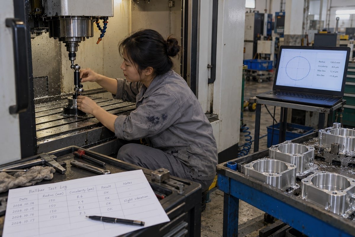
Many buyers assume "CNC" means "precise." It does not. A machine can position its spindle beautifully and still make a wrong part. Tool deflection, clamping distortion, a dirty datum, or a mistyped offset will defeat any machine. So before we change anything, we build a measurement baseline.
Separate accuracy from repeatability
Accuracy is how close the result sits to the nominal dimension. Repeatability is how tightly repeated results cluster. A process can be very repeatable and still wrong. That case is good news, because a stable offset is easy to correct. The hard case is a wide scatter, because the cause is hiding somewhere in the system.
Match the symptom to the likely cause
| Symptom you see | Error type | Most likely causes | First check |
|---|---|---|---|
| Every part off by the same amount | Systematic | Tool offset, pitch error, axis alignment, squareness | Re-measure the tool, verify work offset, check geometry |
| Dimension drifts steadily during a run | Thermal or wear | Spindle growth, coolant temperature, flank wear | Compare first-off and last-off, log spindle temperature |
| Results scatter with no pattern | Random | Chips under the fixture, uneven workpiece clamping, gauge noise | Clean datums, check clamping torque, run a gauge study |
| Chatter marks, oversize corners | Dynamic | Vibration, tool deflection, servo following error | Shorten tool stick-out, reduce radial engagement, check look-ahead |
Diagnose the machine itself
We use a calibrated Coordinate Measuring Machine 3 or bore gauges for the parts. For the machine, we rely on ballbar testing and laser interferometry. These reveal backlash, pitch error, and squareness. Backlash compensation and pitch tables in the control can correct what we measure. But compensation cannot fix a loose bearing or a worn guideway. Physical causes come first.
Spindle runout deserves its own check. Runout at the tool tip creates unequal chip loads, so one flute cuts more than another. Surface finish and size both suffer.
Thermal stability is the quietest killer. One illustration in the literature uses a 1°C gradient across a 10 m machine bed to produce roughly 0.1 mm of error; the figure depends on material and geometry, but it shows the scale. Some precision shops cite an environment near 20 ± 2°C and 50 ± 5% humidity. We do not treat that as a universal rule. For open-tolerance work, a standard warm-up routine and a stable coolant temperature often do the job. Measure the drift before you pay for climate control. For long-term projects, volumetric error compensation and active vibration isolation under the foundation are worthwhile upgrades, but only after basic machine tool calibration is current.
What tolerances can I realistically achieve with 3-axis, 4-axis, and 5-axis CNC machining?
Last quarter, a German project engineer asked us whether 5-axis automatically means tighter tolerance. Our answer was no. Fewer setups help, but rotary-axis calibration decides the result.
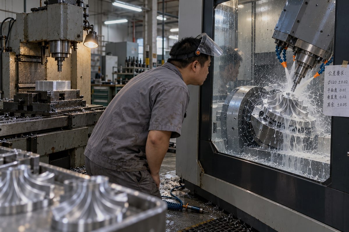
Realistic tolerances depend more on machine condition, material, and feature size than on axis count. Well-maintained 3-axis milling commonly holds ±0.01 mm on simple features; 4-axis adds indexing repeatability; 5-axis reduces datum-transfer errors on complex parts, reaching 0.005 mm when rotary axes are calibrated.
| Configuration | Best suited for | Practical tolerance on critical features | Main accuracy risk |
|---|---|---|---|
| 3-axis milling | Prismatic parts, plates, housings, mold bases | Down to ±0.01 mm with good setup | Multiple setups stack datum errors |
| 4-axis milling | Shafts, cylindrical housings, radial hole patterns | Similar to 3-axis plus indexing repeatability | Rotary indexing accuracy and part runout |
| 5-axis milling | Impellers, turbocharger parts, undercuts, compound angles | 0.01 to 0.005 mm on calibrated machines | Rotary-axis kinematic errors, longer tool stick-out |
Why axis count is not the whole story
On our CNC milling line, we quote 0.01 to 0.005 mm for demanding features regardless of axis count. What changes is how we get there. A 3-axis part with five sides needs five setups. Each flip re-establishes the datum, and each datum transfer adds a little error. A 5-axis machine finishes those sides in one clamping, so the relationship between features is tighter. That is the real benefit for optical housings or a mold base full of bores that must align.
But a 5-axis machine carries two more axes that can be wrong. If the rotary centers are not calibrated, every tilted cut inherits that error. A simple 3-axis setup with fewer transformations can be the safer choice for a plate-type part. We decide per drawing, not per marketing brochure.
What tightens or loosens the number
Material matters. Aluminum cuts easily but moves with heat and clamping. Stainless and titanium cut slower and generate more heat. Thin walls flex. A 0.5 mm wall will not hold the same tolerance as a 10 mm block, no matter the machine. Feature size matters too. General tolerance standards such as ISO 2768 4 widen the band as dimensions grow, and GD&T standards let you tighten only the features that truly need it. That is the single best cost lever a buyer has.
Cutting tool geometry and feed rate optimization shape the final number as well. Climb milling, tangential lead-ins, and look-ahead control keep the chip load constant and stop corners from overshooting. Cryogenic coolant delivery can improve dimensional stability on heat-sensitive aerospace alloys, but it is a specialized option, not a baseline requirement. Rigid holders and vibration damping in the setup usually deliver more for less.
How do I choose the right supplier to ensure consistent precision in batch production?
Price pressure is real. When we quote a 500-piece batch, we weigh cheaper tooling against the cost of a dimension drifting mid-run and stalling a customer's assembly line.
Choose a supplier that proves repeatability, not just a good first sample. Ask for ISO 9001 certification, machine calibration records, first article inspection reports, SPC data with Cpk targets, documented tool-life and offset procedures, and DFM feedback before quoting. Consistent tolerances in batch production come from process discipline.
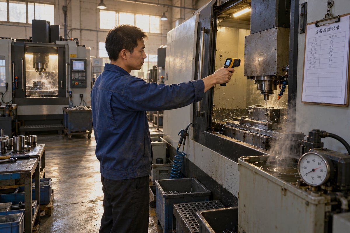
The most common complaint we hear from buyers in the US and Germany is simple. The sample was perfect. The batch was not. Hole positions wandered, threads went tight, burrs appeared on part 80. The sample proved the supplier could make one good part. It said nothing about the next hundred. Our own position, after more than twenty years of exporting, is that consistently stable dimensional tolerance is the only metric that matters in production. One perfect part is a demonstration. Three hundred identical parts are a process.
Why a good sample turns into a bad batch
The sample usually gets the shop's best operator, a fresh tool, and a cold machine. Batch production gets a tired tool, a warm spindle, and a second-shift operator. The gaps between those two conditions are where drift lives. A supplier closes those gaps with:
- A defined warm-up cycle before every run.
- Tool-life limits by part count or cutting time, with tool wear compensation applied in controlled steps.
- Repeatable workpiece clamping, often with zero-point or hydraulic fixtures so each part sits in the same place with the same force.
- Roughing and finishing separated, so residual stress and heat from heavy cuts do not land in the final dimension.
- First-off, in-process, and last-off measurement with action limits set inside the tolerance.
One published approach samples three parts per hour and targets a Cpk of at least 1.33. We treat that as a starting point, not a law. The sampling plan should follow your tolerance, your volume, and the cost of a bad part reaching your line.
Questions that expose real process control
| Question to ask | Answer that signals control | Red flag |
|---|---|---|
| How do you manage tool wear during a long run? | Tool-life table, offset adjustment limits, automated tool measurement | "The operator watches it" |
| How is the fixture designed for my part? | Dedicated or zero-point fixture, 3-2-1 location, torque-controlled clamps | Vise and parallels for a thin-walled housing |
| When was the machine last calibrated? | Ballbar or laser records with dates and results | No records |
| What tool holders do you use for finishing? | Shrink-fit or hydraulic holders, runout checked (some guides cite 3 μm as a high-precision ceiling) | Worn collets, no runout check |
| Can you certify the material? | Mill certificate traceable to the lot, 6061 is 6061, 316 is not 304 | "Same grade, different name" |
| Will you review my drawing first? | DFM feedback on tolerances, datums, and cost drivers before quoting | Quote with no questions asked |
Dedicated fixtures and modular systems are a genuine trade-off. A dedicated fixture usually gives better repeatability for high volume. Modular and zero-point systems change over faster and cost less for high-mix work. Ask which one the supplier plans to use and why. Acoustic emission sensors and AI-based wear prediction are useful on long aerospace runs, but a disciplined tool-life table and first-off inspection catch most problems at a fraction of the cost. Our ISO 9001:2015 system, our DFM review on every uploaded drawing, and our "German Quality, Asia Price" positioning exist precisely because buyers have been burned by shops that skipped these steps.
What quality inspection methods can I request to verify CNC machining accuracy before shipment?
One hard lesson shaped our outgoing inspection: a Coordinate Measuring Machine report means little if parts were measured warm, straight off the spindle. Now every critical batch rests first.
Request a first article inspection report, CMM dimensional reports against GD&T callouts, material certificates, surface-finish and thread gauge checks, in-process probing records, and an outgoing inspection sampling plan. Ask that measurements be taken on temperature-stabilized parts with calibrated instruments and traceable serial or lot numbers.
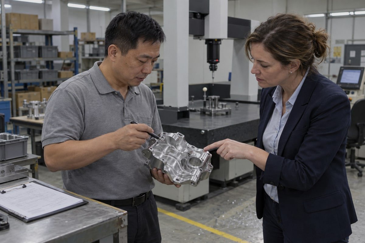
Inspection does not create accuracy. It confirms it. That distinction matters, because a buyer who only asks for a final CMM report is checking the answer without seeing the work. We encourage customers to ask for evidence from three stages: during setup, during the run, and before the box is sealed.
Match the method to your tolerance and volume
| Method | Typical use | Response time | Limits |
|---|---|---|---|
| Manual gauges (micrometer, bore gauge, thread gauge) | Open tolerances, quick first-off checks, go/no-go on threads | Immediate | Operator dependent, limited for position and profile |
| On-machine probing | Work offset verification, bore size, drift detection in long runs | Immediate, in-cycle | Needs clean surfaces and probe calibration; cannot replace final inspection |
| Coordinate Measuring Machine | Full GD&T evaluation, first article, batch sampling | Minutes to hours per part | Parts must be temperature-stabilized; throughput limited |
| Optical or vision measurement | Small features, thin parts, profiles that a stylus could deflect | Fast | Edge definition and lighting sensitivity |
Documents worth putting in the purchase order
A first article inspection report ties every drawing dimension to a measured value. A material certificate traceable to the lot stops the 304-for-316 substitution that worries so many medical and food-equipment buyers. A surface-finish 5 check, with roughness values on functional faces, protects sealing surfaces and optical bores. An outgoing inspection record shows the sampling frequency and the result of each sample. For long-term programs, SPC charts with Cp and Cpk tell you whether the process is stable or just lucky.
Ask about measurement uncertainty
A gauge that varies by a quarter of your tolerance cannot tell you much about your parts. We run gauge studies on the instruments we use for tight features, and we calibrate probes and CMM styli on a schedule. Buyers rarely ask about this, but it separates a real quality system from a printed report.
Finally, inspection ends at packaging. A perfect part scratched in transit is a reject on arrival. We pack precision parts in individual cavities or VCI-protected bags, label them by lot, and back every shipment with a 30-day warranty. If something does arrive wrong, fast rework or replacement is part of the quality system, not an afterthought.
Conclusion
Inaccurate parts waste schedules and trust. Fix setups, heat, tooling, and measurement first; invest in calibration and probing next. Send us your drawing for DFM feedback and a tolerance review.
Footnotes
1. Authoritative Wikipedia entry providing a comprehensive overview of global GD&T standards, including ASME and ISO. ↩︎
2. Explanation of quality documentation that verifies the chemical and physical properties of raw materials. ↩︎
3. Authoritative overview of CMM technology used for high-precision dimensional inspection of CNC parts. ↩︎
4. Official international standard for general geometrical tolerances in manufacturing and CNC machining. ↩︎
5. International standard for surface texture and finish requirements in precision engineering. ↩︎

 Slovenščina
 English
 Italiano
 Français
 日本語
 Deutsch (Sie)
 Español
 Русский
 العربية
 Български
 Čeština
 Dansk
 Suomi
 עִבְרִית
 हिन्दी
 Nederlands
 Português
 Română
 Slovenčina
 Svenska
 ไทย
 Tiếng Việt
 Türkçe