
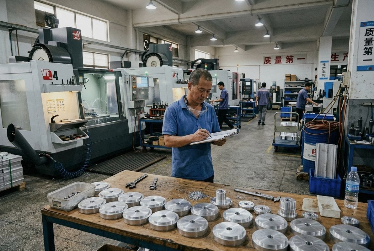
Every week, our engineering team reviews dozens of new part drawings from buyers worldwide — and the most common question we hear is: “What actually happens to my design once it hits your factory floor?” It is a fair question, because a single misstep between the digital file and the finished part can mean scrapped material, blown deadlines, and budget overruns that ripple through an entire project. digital CAD model 1
The CNC machining process transforms a digital CAD model into a finished physical part through five core steps: designing the part, programming toolpaths with CAM software, setting up the machine with the correct workpiece material and cutting tools, executing the G-code program, and performing rigorous quality inspection to verify tolerances.
Below, I will walk you through each stage the way it actually unfolds in our Dongguan facility — from the moment we open your drawing to the moment your parts ship. Let’s break it down.
How do I prepare my CAD drawings to ensure they are ready for the CNC machining process?
A lesson we learned early on is that 80 percent of production delays trace back to a drawing issue, not a machine issue. When our DFM engineers flag a potential problem before programming even starts, it saves everyone time and money.
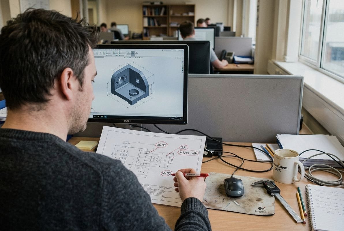
To prepare CAD drawings for CNC machining, export your 3D model as a STEP or IGES file, include a fully dimensioned 2D drawing with tolerances, specify the workpiece material, surface finish, and any critical features — then request a Design for Manufacturability review before production begins.
Why File Format Matters
CAD software varies widely. Some buyers use SolidWorks, others use Fusion 360, Creo, or even AutoCAD. The safest approach is to export a neutral file format. STEP files 2 preserve full 3D geometry and are universally compatible with most CAM software 3. IGES is another option, though it can sometimes lose surface data on complex curved features.
We always ask for two things: the native 3D file (STEP preferred) and a 2D PDF drawing. The 3D file feeds directly into our CAM programming. The 2D drawing is the contract — it tells us which dimensions are critical, where tolerances are tight, and what surface finish you need.
What Your Drawing Should Include
Missing information is the single biggest source of back-and-forth emails. Here is what we recommend including on every drawing:
| Drawing Element | Why It Matters | Common Mistake |
|---|---|---|
| Material callout (e.g., AL6061-T6) | Determines cutting tools, speeds, and feeds | Writing only "aluminum" with no grade |
| Tolerance callout on critical dims | Tells us which features need extra care | Assuming ±0.01 mm everywhere (raises cost) |
| Surface finish (Ra value or standard) | Guides post-processing decisions | Leaving it blank — we default to as-machined |
| Thread specs (type, pitch, class) | Prevents rework on mating features | Omitting thread depth or class of fit |
| Geometric tolerances (GD&T) | Controls form, position, and orientation | Using only linear dims on complex parts |
| Quantity and batch size | Affects fixturing strategy and pricing | Not specifying prototype vs. production run |
The DFM Review Step Most Buyers Skip
Once we receive your files, our engineers run a full Design for Manufacturability analysis 4. This is not a sales gimmick — it is a structured review where we check wall thickness, internal corner radii, hole depth-to-diameter ratios, and undercuts. If a feature will require a special tool or an extra setup, we flag it and suggest alternatives that achieve the same function at lower cost.
For example, a US-based automation equipment buyer once sent us a bracket design with 0.5 mm internal corner radii on deep pockets. Our smallest end mill for that depth was 1 mm diameter, which leaves a 0.5 mm radius — right on the edge. We suggested opening the radius to 0.8 mm, which allowed a more rigid tool, faster feed rates, and zero risk of tool breakage. The part function was unchanged. The cost dropped 15 percent.
Bottom line: invest ten extra minutes in your drawing package, and you will save days on the production side.
How does the CNC software translate my technical specifications into actual machine movements?
One trade-off our programmers weigh daily is speed versus surface quality. A more aggressive toolpath removes material faster but can leave visible tool marks on critical surfaces — so we program different strategies for roughing and finishing passes on the same part.
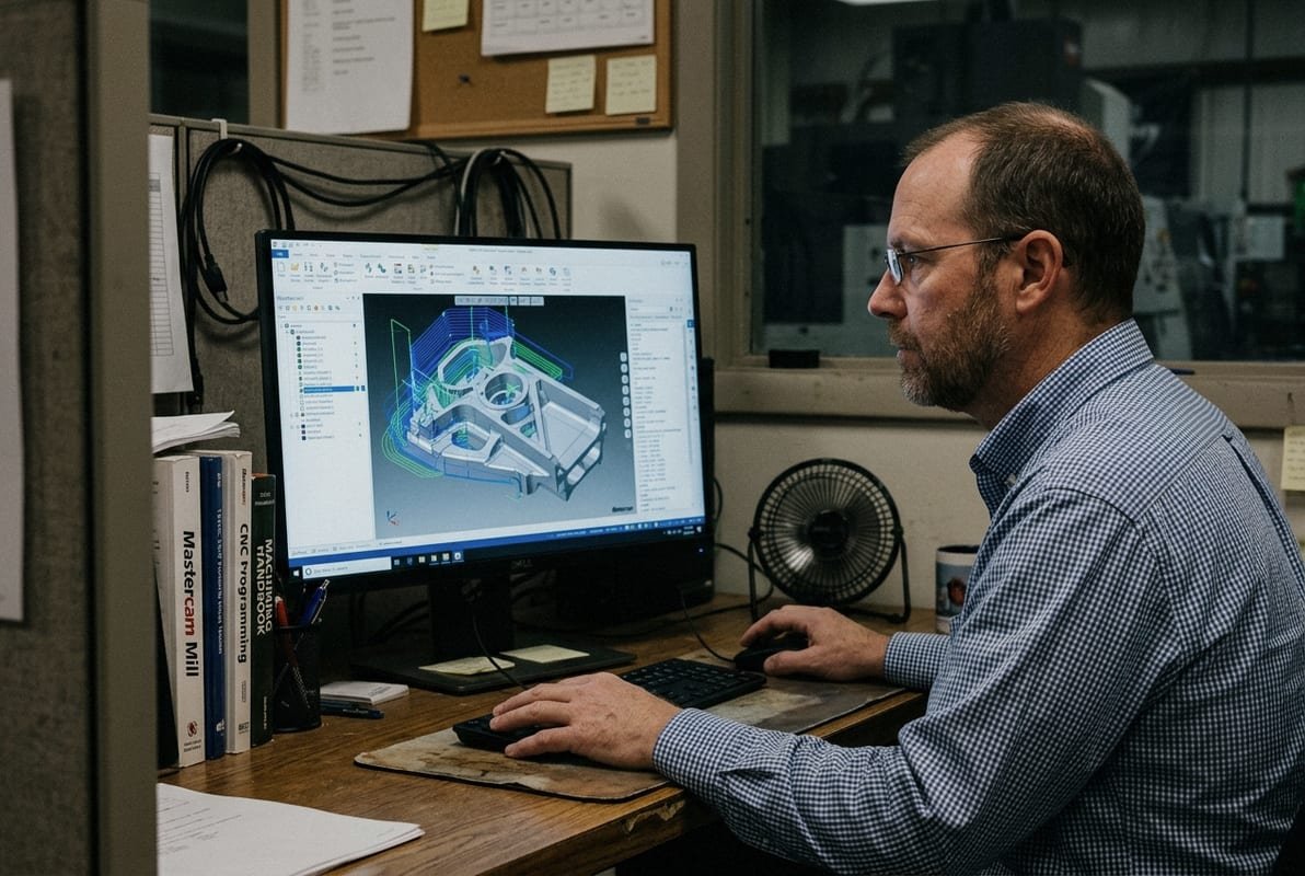
CAM software reads your 3D CAD model and generates toolpaths — precise movement instructions encoded as G-code — that tell the CNC machine exactly where to move each cutting tool, how fast to spin, how deep to cut, and in what sequence, turning your design into repeatable physical geometry.
From CAD Model to G-Code
The journey starts when our programmer imports your STEP file into our CAM software. The software displays the 3D model and allows the programmer to define each machining operation: face milling the top, pocketing an internal cavity, drilling bolt holes, contouring an outer profile, and so on.
For each operation, the programmer selects:
- The cutting tool (type, diameter, flute count, coating)
- The spindle speed (RPM)
- The feed rate (mm per minute)
- The depth of cut per pass
- The toolpath strategy (adaptive clearing, contour, pencil, scallop, etc.)
The CAM software then calculates the exact path the tool tip will trace through space. This path is exported through a post-processor — a translator that converts the generic toolpath data into machine-specific Código G 5. Different CNC machines (Fanuc, Siemens, Haas) speak slightly different dialects of G-code, so the post-processor is essential.
What G-Code Actually Looks Like
G-code is a line-by-line instruction set. Here is a simplified example:
| G-Code Line | What It Does |
|---|---|
| G90 | Sets absolute positioning mode |
| G21 | Sets units to millimeters |
| S8000 M03 | Spins spindle at 8,000 RPM clockwise |
| G00 X0 Y0 Z5.0 | Rapid move to start position |
| G01 Z-2.0 F300 | Linear cut down 2 mm at 300 mm/min |
| G01 X50.0 F600 | Linear cut across 50 mm at 600 mm/min |
| M05 | Spindle stop |
| M30 | Program end |
Every line is a command. The machine reads thousands of these lines per part. More complex parts — like the radial impeller wheels we machine from solid aluminum billets — can have programs with over 100,000 lines of G-code.
Simulation Before Cutting
Before any metal is cut, we run a full simulation inside the CAM software. The simulation shows the virtual tool moving through the virtual stock, material removal in real time, and collision detection between the tool holder, spindle, and fixtures. This step catches crashes, gouges, and air-cutting inefficiencies before they waste real material.
I cannot overstate how important this is. A five-axis program for a turbine wheel might take four hours to run. If we discover a collision at hour three on a real machine, we have lost the raw material, the machine time, and the delivery schedule. Simulation eliminates that risk almost entirely.
Roughing vs. Finishing Strategies
In subtractive manufacturing 6, we rarely go straight to the final dimension. Roughing passes remove the bulk of the material quickly using larger tools and aggressive depths. Finishing passes then come in with finer tools, lighter cuts, and slower feeds to hit the final tolerance and surface finish.
This two-stage approach matters for parts like the precision cylindrical components with multi-level circular features that we produce — the roughing pass shapes the overall profile, and the finishing pass dials in the 0.01 mm tolerances our aerospace and medical device clients require.
What steps does the factory take to set up the machines for my custom parts?
A buyer from Germany once told me his previous supplier ruined a batch of stainless steel housings because the workpiece shifted mid-cut — the fixturing was not secure enough for the lateral cutting forces. That single incident cost weeks and thousands of dollars. Machine setup is where theory meets reality, and carelessness here is unforgiving.
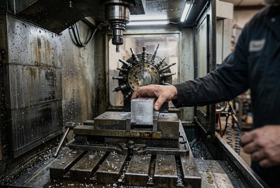
Machine setup involves securing the raw workpiece onto the CNC machine using vises, clamps, or custom fixtures, loading the correct cutting tools into the spindle or turret, setting work coordinates and tool length offsets, and running a first-article test cut to confirm everything aligns with the programmed G-code.
Step-by-Step Setup Sequence
Here is the actual sequence our operators follow for a typical CNC milling job:
- Select the raw stock. We match the material grade to the drawing callout — 6061-T6 aluminum, 304 stainless steel, Grade 5 titanium, or whatever the spec requires. We verify it with a material certificate 7 before any cutting begins.
- Mount the workpiece. Depending on the part geometry, we use a precision vise, step clamps, vacuum table, or a custom-machined fixture. For CNC turning jobs, the stock is chucked in a lathe collet or jaw chuck.
- Load cutting tools. Each tool goes into its designated holder and magazine pocket. We pre-set tool lengths using an offline tool presetter so the machine knows the exact offset.
- Set work coordinates. The operator probes the workpiece surface to establish X, Y, and Z zero points. work coordinates 8 This tells the machine exactly where the material is.
- Dry run or slow run. We often run the program at reduced speed without cutting to verify clearances.
- First-article cut. The first part is machined, measured, and compared to the drawing. Only after this part passes inspection do we proceed with the batch.
Fixturing Strategies for Different Part Types
The fixturing approach changes dramatically based on part complexity. Here is a comparison:
| Part Type | Typical Fixturing Method | Key Consideration |
|---|---|---|
| Flat plate / bracket | Precision vise or step clamps | Ensure parallel surfaces; avoid clamping on thin walls |
| Cylindrical shaft | Lathe chuck (3-jaw or collet) | Minimize runout; check concentricity |
| Complex 5-axis part | Custom fixture or soft jaws | Multiple datums; accessibility for tool clearance |
| Thin-walled housing | Vacuum fixture or distributed clamps | Prevent deflection under cutting forces |
| Impeller / turbine wheel | Dedicated mandrel or expanding arbor | Balance clamping force with access to blade geometry |
For the aluminum impeller wheels we machine, fixturing is especially critical. The thin blades can deflect if clamping force is not evenly distributed. We use a custom mandrel that supports the hub bore while leaving all blade passages accessible to the five-axis spindle.
Tool Management
We maintain a tool library with hundreds of end mills, drills, reamers, taps, and boring bars in various diameters and coatings. Coated carbide tools handle aluminum at high speeds. For stainless steel and titanium, we use tools with TiAlN or AlCrN coatings that resist heat buildup.
Tool wear is tracked per part count. We replace tools proactively — not after a part fails inspection, but before the edge degrades enough to affect surface finish or dimensional accuracy. This is part of what makes the CNC machining process a closed-loop system: programming, clamping, cutting, in-process measurement, and dynamic adjustment all feed into each other continuously.
How can I be sure my finished parts meet the exact tolerances and material specs I requested?
During a recent project for an optical equipment manufacturer in the US, the buyer required a surface flatness of 0.005 mm across a 120 mm aluminum plate. Standard machining would not guarantee that. We added a stress-relief step between roughing and finishing, and verified the result on our CMM. The part passed — and the buyer reordered within two months.
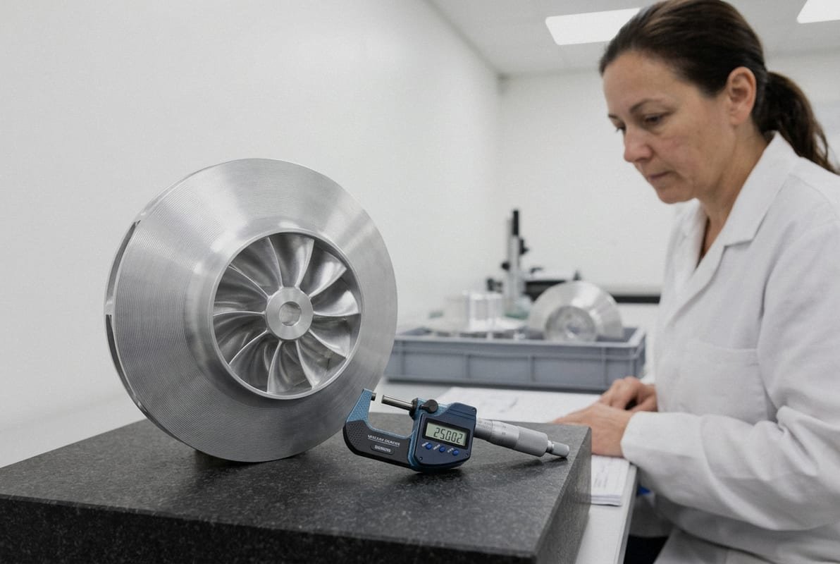
You can verify your parts meet spec by requesting a First Article Inspection (FAI) report with CMM data, dimensional inspection records, material certifications, and surface finish measurements — and by partnering with an ISO 9001:2015 certified factory that integrates quality checks at every production stage.
In-Process Inspection vs. Final Inspection
Quality is not something we bolt on at the end. It starts during setup and continues through every phase.
In-process inspection means the operator checks critical dimensions at regular intervals during the run — after the first piece, after every tenth piece, or after a tool change. We use digital calipers, micrometers, bore gauges, and surface roughness testers right on the shop floor.
Final inspection is a comprehensive check of every critical dimension on the finished part. For high-precision orders, we use a Coordinate Measuring Machine (CMM) 9, which probes the part at hundreds of points and compares the measured geometry to the CAD model.
What Documentation We Provide
| Document | What It Contains | When It Is Provided |
|---|---|---|
| First Article Inspection (FAI) report | Measured values for every critical dimension vs. drawing nominal | After first piece approval |
| CMM report | 3D point cloud data and deviation analysis | With FAI or upon request |
| Material certificate (Mill Cert) | Material grade, chemical composition, heat lot number | With shipment |
| Surface finish report | Ra measurements on specified surfaces | With FAI or upon request |
| Dimensional inspection report | Batch sampling measurements for production runs | With every shipment |
How We Catch Problems Before They Reach You
Our ISO 9001:2015 system 10 defines control points at each stage. But beyond the system, what really matters is experience. After twenty years of CNC machining, our team can often predict where a part will go out of tolerance — a long, thin feature that deflects, a deep pocket that traps heat, a thread that galls in certain stainless grades.
CNC machining is not a one-button operation. It is a closed-loop system of programming, clamping, cutting, post-processing, in-process measurement, and dynamic adjustment. What truly separates one factory from another is whether the team has enough experience to anticipate problems before they happen — and prevent scrap and rework instead of reacting to it.
Post-Processing and Surface Finishing
After machining, many parts need additional steps: deburring sharp edges, bead blasting for a uniform matte texture, anodizing aluminum for corrosion resistance, or nickel plating steel for durability. Each of these processes can affect dimensions. For example, anodizing adds roughly 0.01–0.025 mm of coating thickness. We account for this in the machining program so the final coated dimension still falls within your tolerance band.
For the precision aluminum components with satin finishes and fine circular tool marks that we regularly produce, we carefully control the finishing pass to deliver a consistent surface texture without additional polishing — reducing lead time and cost while maintaining the high-tech industrial appearance our buyers need.
Common Material Verification Methods
We never assume the raw stock is correct just because the label says so. For critical orders, we run handheld XRF analysis to confirm the alloy composition matches the material certificate. This guards against the material substitution risk that many overseas buyers worry about — such as a supplier swapping 6061 aluminum for a cheaper grade, or mixing 304 and 316 stainless steel.
Conclusion
The CNC machining process is a coordinated chain — from CAD preparation through programming, machine setup, cutting, and rigorous inspection. Each link depends on the one before it. Choosing a partner with deep experience across all five stages is how you protect your tolerances, your timeline, and your budget.
Footnotes
1. Explains the role of CAD models in manufacturing. ↩︎
2. Provides information on a common 3D model file format. ↩︎
3. Defines CAM software and its function in CNC. ↩︎
4. Details the importance of DFM in preventing production issues. ↩︎
5. Explains G-code as the language of CNC machines. ↩︎
6. Describes the fundamental process of material removal. ↩︎
7. Replaced with a working link defining a Material Test Report (MTR), which is synonymous with a material certificate. ↩︎
8. Clarifies the setup process for machine operation. ↩︎
9. Replaced with a working Wikipedia link, an authoritative source, defining Coordinate Measuring Machine (CMM). ↩︎
10. Highlights a standard for quality management in manufacturing. ↩︎

 Português
  English
  Italiano
  Français
  日本語
日本語  Deutsch (Sie)
  Español
  Русский
  العربية
  Български
  Čeština
  Dansk
Dansk  Suomi
Suomi  עִבְרִית
  हिन्दी
  Nederlands
  Română
  Slovenčina
  Svenska
  ไทย
ไทย  Tiếng Việt
  Türkçe
  Slovenščina