

A single micron of deviation once cost one of our aerospace clients an entire batch of turbine components high-precision industrial parts manufacturing 1. That experience taught our engineering team a hard lesson: CNC machining accuracy 2 is not just a spec on paper — it determines whether parts function or fail.
CNC machining is exceptionally accurate for high-precision industrial parts manufacturing, with standard machines achieving tolerances of ±0.005 mm and high-end 5-axis systems reaching 1–5 microns. Achieving this level of dimensional accuracy depends on machine calibration, material choice, tooling, and rigorous quality control throughout the process.
This article breaks down the real tolerance ranges you can expect, how multi-axis machining improves accuracy, how to verify your supplier’s work, and why material selection and DFM feedback matter more than most buyers realize high-end 5-axis systems 3. Let’s get into the details.
What specific tolerance ranges can I achieve for my high-precision CNC machined parts?
One question we hear almost weekly from procurement managers in the US and Europe is straightforward: "What tolerances can you actually hold?" It is the first thing buyers ask because machining tolerances define whether a part will assemble, seal, rotate, or fail.
For high-precision CNC machined parts, standard machines hold ±0.005 mm (±0.0002 in), high-end equipment reaches ±0.002 mm, and ultra-precision systems used in aerospace and medical applications achieve 1–5 microns (±0.001–0.005 mm). Material type and machine condition directly affect these ranges.
Understanding Precision vs. Accuracy
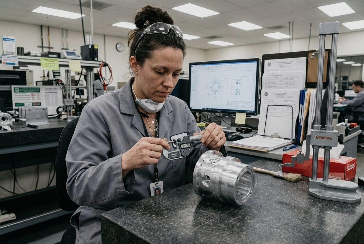
Before we talk numbers, let's clarify two terms buyers often mix up. Precision means repeatability — can the machine produce identical parts over and over? Accuracy means closeness to the target dimension on your drawing. You need both. A machine can be precise but inaccurate if it consistently makes the same wrong cut. Our ISO 9001:2015 quality system 4 tracks both metrics on every production run.
Tolerance Ranges by Machine Class
Here is a practical breakdown of what different CNC systems can deliver:
| Machine Class | Typical Tolerance | Common Applications |
|---|---|---|
| Standard CNC (3-axis) | ±0.005 mm (±0.0002 in) | General industrial parts, housings, brackets |
| High-End CNC (4/5-axis) | ±0.002 mm (±0.00008 in) | Complex structural components, optical mounts |
| Ultra-Precision CNC 5 | ±0.001–0.005 mm (1–5 microns) | Aerospace turbine blades, medical implants |
| Sub-Micron Systems | < 1 micron | Semiconductor, ultra-fine optics |
On our production floor in Dongguan, our 3-axis, 4-axis, and 5-axis machines routinely hold tolerances of 0.01–0.005 mm. For tighter requirements, we use specialized tooling and run slower cutting parameters to reduce tool deflection and thermal distortion.
What Drives Tolerance Limits
Machining tolerances are not just about the machine. Several factors work together:
- Machine condition. Worn spindles and ball screws cause drift. We schedule preventive maintenance to keep axis accuracy around 0.01 mm or better.
- Cutting tool quality. Tool wear changes the geometry of each cut. We monitor tool life and replace inserts on a fixed schedule, not when they fail.
- Material properties. Aluminum machines cleanly and holds tight tolerances. Stainless steel and titanium expand under heat, so we adjust feed rates and cooling strategy.
- Workholding and fixturing. A part that moves even 0.02 mm in the fixture ruins the entire run. We design custom fixtures for complex parts.
- Environmental control. Temperature swings of just 2°C can shift dimensions on precision aluminum parts. Our shop maintains stable conditions.
Cost vs. Tolerance Trade-Off
Tighter machining tolerances cost more. It is that simple. Slower speeds, finer tools, extra inspection steps, and climate control all add up. Smart buyers specify tight tolerances only on critical features — mating surfaces, bore diameters, seal grooves — and leave non-functional surfaces at standard tolerances. This approach saves money without sacrificing function. When we provide DFM feedback, tolerance optimization is one of the first things we review.
How does 5-axis machining improve the accuracy of my complex structural components?
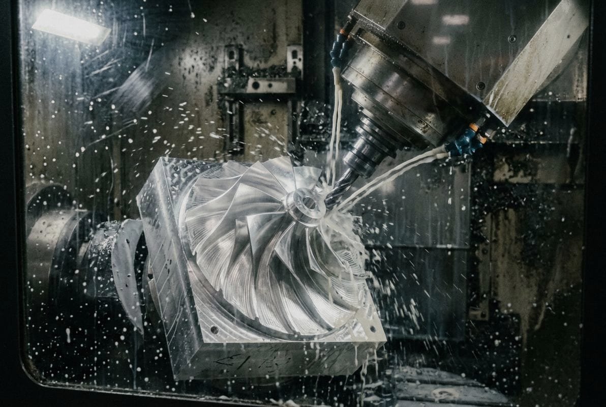
Last year, a US-based automation equipment company sent us a radial impeller design with compound curved surfaces and undercuts that no 3-axis setup could reach in a single clamping. That project is a perfect example of why multi-axis machining exists.
5-axis CNC machining improves accuracy on complex structural components by machining multiple faces in a single setup, eliminating repositioning errors that typically add ±0.02–0.05 mm of deviation. It also enables shorter, stiffer cutting tools that reduce deflection and vibration, resulting in better surface finish and tighter geometric tolerances.
Why Repositioning Kills Accuracy
On a 3-axis machine, a complex part might need three, four, or even five separate setups. Every time the operator unclamps and reclamps the workpiece, they introduce alignment error. Even with precision vises and dowel pins, repositioning typically adds 0.02–0.05 mm of cumulative deviation. On a 5-axis machine, the part stays fixtured once. The two additional rotary axes bring the cutting tool to every surface without moving the workpiece. This single-setup approach is the single biggest accuracy advantage of 5-axis machining.
Shorter Tools, Less Deflection
Complex geometry often requires reaching into deep pockets or machining at steep angles. On 3-axis machines, this means long, thin tools that flex under cutting forces. Tool deflection directly degrades dimensional accuracy and surface finish. With 5-axis capability, the machine tilts the spindle to maintain an optimal tool angle. This allows shorter, more rigid tools. Less deflection means tighter tolerances and smoother surfaces — often achieving Ra 0.8 µm or better without secondary finishing.
3-Axis vs. 5-Axis: A Practical Comparison
| Factor | 3-Axis CNC | 5-Axis CNC |
|---|---|---|
| Number of setups for complex part | 3–5 | 1 |
| Repositioning error | ±0.02–0.05 mm | Eliminated |
| Tool length required | Longer (more deflection) | Shorter (less deflection) |
| Surface finish quality | Good (Ra 1.6 µm typical) | Excellent (Ra 0.8 µm typical) |
| Geometric tolerance capability | Standard | High (compound angles, true position) |
| Cycle time for complex parts | Longer | Shorter |
| Machine cost | Lower | Higher |
When 5-Axis Is Worth the Investment
Not every part needs 5-axis machining. Simple plates, shafts, and housings run perfectly on 3-axis machines. But when your design has compound curves, tight geometric tolerances (like true position within 0.01 mm), or features on multiple faces that must align precisely, 5-axis is the right choice. Components like turbine impellers, aerospace brackets, optical instrument housings, and medical device bodies all benefit. On our floor, we match each job to the right machine class based on the drawing — not because we want to charge more, but because accuracy depends on using the correct process. For a deeper dive into how these machine configurations compare, see our guide on the differences between 3-axis, 4-axis, and 5-axis CNC machining.
The Software Side
5-axis accuracy also depends heavily on CAM software. The tool paths must account for simultaneous motion of all five axes without collisions or overcutting. Our programmers use advanced CAM systems that simulate the entire machining process before metal is cut. This virtual verification catches errors that would otherwise show up as scrap. Post-processor accuracy, machine kinematics modeling, and thermal compensation algorithms all play roles in delivering the final dimensional accuracy.
How can I verify that my supplier is meeting the exact dimensional specs on my drawings?
A procurement manager we work with in the Midwest once told me: "I trust but verify. If a supplier can't prove the numbers, they don't get the repeat order." That mindset is exactly right, and it shapes how we approach quality control and documentation.
To verify your supplier meets dimensional specs, request CMM (Coordinate Measuring Machine) inspection reports, First Article Inspection (FAI) documentation, material certifications, and in-process measurement records. Cross-check critical dimensions against your drawing tolerances, and consider third-party metrology audits for high-value or safety-critical parts.
The Inspection Toolbox
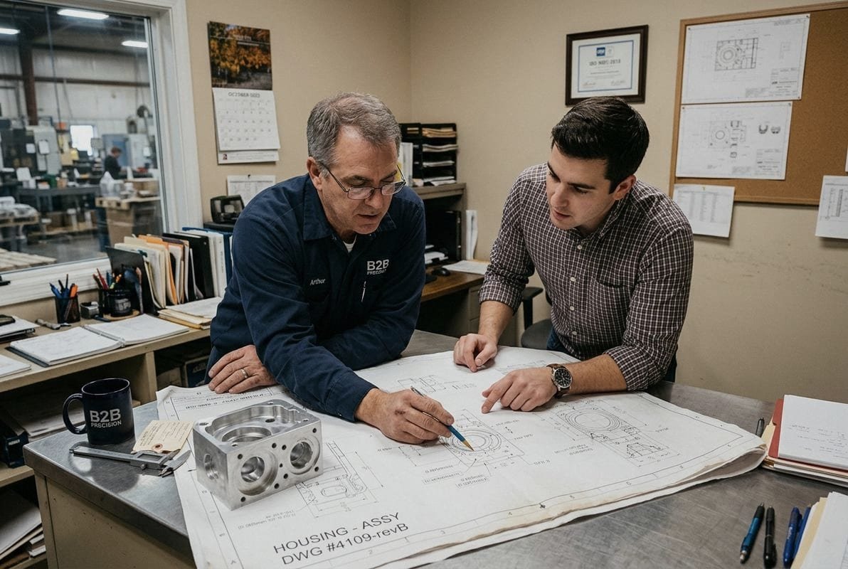
Different features require different measurement methods. Here is how we verify dimensions across various tolerance levels:
| Measurement Method | Typical Accuracy | Best For |
|---|---|---|
| Digital calipers | ±0.02 mm | External dimensions, lengths, diameters |
| Micrometers | ±0.005 mm | Precision diameters, thickness |
| CMM (Coordinate Measuring Machine) | ±0.002–0.005 mm | Complex 3D geometry, true position, profiles |
| Optical comparator / Vision system | ±0.005 mm | 2D profiles, radii, edge features |
| Surface roughness tester | Ra 0.05 µm resolution | Surface finish verification |
| Laser interferometry | Sub-micron | Machine calibration, ultra-precision verification |
| Pin/ring gauges | Go/No-Go | Thread and bore verification |
We use CMM inspection as the standard for critical dimensions on every production order. Our team generates a full dimensional report that maps each measured value against the drawing spec. Buyers can see at a glance which features pass and where any deviation exists.
What to Ask Your Supplier
Here is a practical checklist for verifying your supplier's quality:
- Request the FAI report before mass production. The First Article Inspection should measure every dimension on the drawing — not just a few spot checks.
- Ask for material certificates (Mill Test Reports). These prove the raw material grade matches the specification. No certificate means no traceability.
- Review in-process inspection records. Good suppliers check dimensions during machining, not just at the end. This catches drift before it becomes a batch problem.
- Specify which dimensions are critical. Mark CTQ (Critical to Quality) features on your drawing. This tells the supplier where to focus metrology resources.
- Request photos of surface finish. For anodized, plated, or polished parts, visual documentation prevents disputes about cosmetic quality.
- Consider a third-party audit. For high-value or safety-critical parts, an independent metrology lab can verify the supplier's numbers.
Why Documentation Matters
In our experience exporting to the US and Europe, professional buyers expect a quality package with every shipment. This typically includes a dimensional inspection report, material certificate, surface treatment confirmation, and packing photos. We include these as standard practice. The documentation is not just paperwork — it is proof that every step of the process was controlled. Without it, you are relying entirely on trust, and trust without data is just hope. Our 30-day warranty backs every shipment, but the real quality assurance happens before the parts leave our facility through rigorous inspection at multiple stages.
Repeatability Across Batches
One good sample does not prove a supplier can maintain quality across 500 or 5,000 pieces. Ask about Statistical Process Control (SPC) 7 data for production runs. Consistent Cpk values above 1.33 on critical dimensions indicate the process is stable and centered. If your supplier cannot explain their approach to repeatability, that is a red flag.
How do my material choices and DFM feedback impact the final precision of my parts?
During a recent project for an automotive parts buyer, we recommended switching from 304 stainless steel to 6061-T6 aluminum for a non-corrosive-environment bracket. The result was tighter tolerances at lower cost — and faster delivery. Material choice is not just about strength; it directly impacts what the machine can achieve.
Material selection fundamentally impacts CNC machining precision because each material responds differently to cutting forces, heat generation, and tool wear. Harder materials like titanium increase tool deflection and thermal expansion, while aluminum machines predictably and holds tighter tolerances. DFM feedback from experienced engineers identifies these issues before production, reducing rework and optimizing both cost and dimensional accuracy.
How Material Properties Affect Tolerances
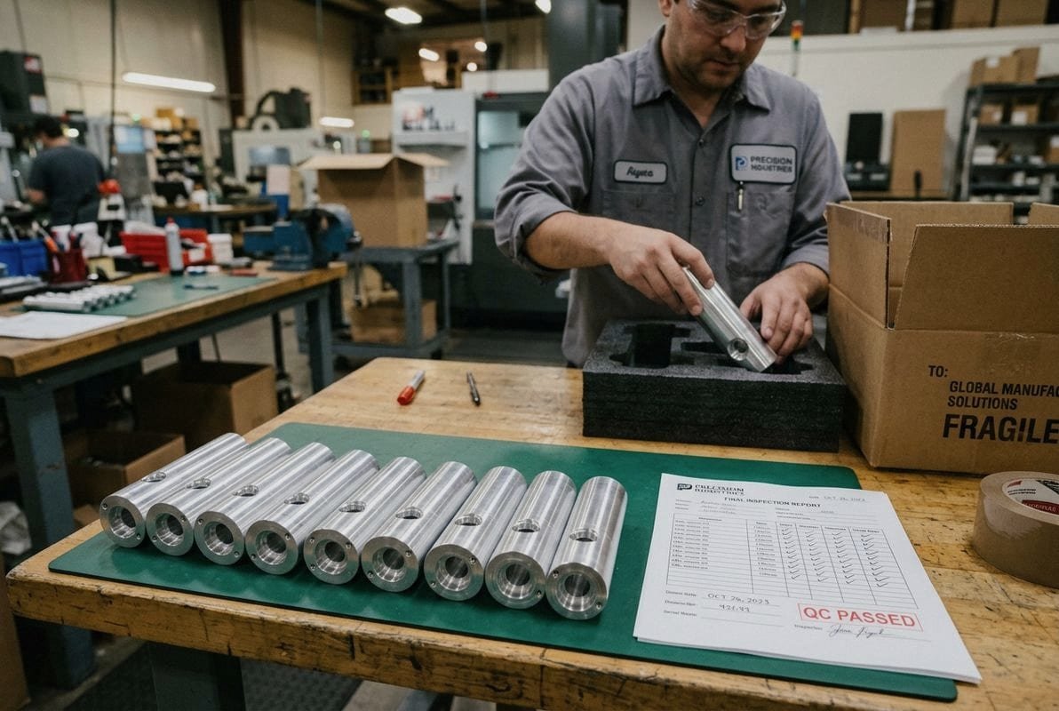
Every material has unique characteristics that influence how accurately it can be machined:
- Thermal expansion. Materials that heat up quickly during cutting expand and then contract as they cool. thermal expansion 8 This causes dimensional drift. Aluminum has high thermal conductivity, so it dissipates heat well. Stainless steel and titanium retain heat, making them harder to hold to tight specs.
- Hardness. Harder materials cause faster tool wear. As the tool wears, the cutting edge changes geometry. This gradually shifts dimensions unless tool offsets are updated or inserts are replaced.
- Internal stresses. Some raw stock has residual stress from rolling or forging. When material is removed, these stresses release and the part warps. Stress-relieved or pre-aged material holds dimensions better.
- Machinability rating. Free-machining alloys like 6061 aluminum and 303 stainless steel cut cleanly with predictable chip formation. Difficult materials like Inconel or PEEK require specialized cutting parameters and generate more variation.
Material Machinability Comparison
| Material | Machinability | Typical Achievable Tolerance | Key Challenge |
|---|---|---|---|
| 6061-T6 Aluminum | Excellent | ±0.005 mm | Burr formation on thin walls |
| 7075 Aluminum | Very Good | ±0.005 mm | Residual stress warping |
| 303 Stainless Steel | Good | ±0.01 mm | Work hardening if feed too slow |
| 316 Stainless Steel | Moderate | ±0.01–0.02 mm | Heat retention, tool wear |
| Titanium (Ti-6Al-4V) | Difficult | ±0.01–0.02 mm | Extreme heat, rapid tool wear |
| PEEK | Moderate | ±0.01 mm | Melting at high speeds |
| Brass (C360) | Excellent | ±0.005 mm | Minimal challenges |
The DFM Advantage
DFM — Design for Manufacturability — is the process where our engineers review your drawings before quoting and flag potential problems. Design for Manufacturability (DFM) 9 This is not about changing your design; it is about catching issues that would hurt precision or raise costs unnecessarily.
Common DFM recommendations we provide include:
- Relaxing non-critical tolerances. If a surface does not mate with another part, holding it to ±0.005 mm wastes time and money. We suggest where standard tolerances are sufficient.
- Adjusting wall thickness. Thin walls below 0.5 mm vibrate during machining. This causes chatter marks and dimensional variation. We recommend minimum thicknesses based on the material and part geometry.
- Optimizing corner radii. Sharp internal corners require small-diameter end mills that wear fast and deflect easily. Slightly larger radii allow stiffer tools and better accuracy.
- Recommending material alternatives. When the application allows, switching from a difficult-to-machine alloy to a friendlier one improves tolerances and reduces lead time.
- Addressing surface finish requirements. Specifying a finer surface finish than needed increases machining time. We help buyers define realistic Ra values for each feature.
Why Skipping DFM Costs More
Buyers who skip the DFM step often discover problems after first articles are made. At that point, redesign means new programming, new tooling, and lost time. In our experience, spending one day on DFM review saves one to two weeks of rework downstream. We provide DFM feedback on every order as a standard part of our process — not as an upsell. It is how we protect both quality and delivery schedules.
Conclusion
CNC machining accuracy for high-precision industrial parts depends on machine capability, material selection, process control, and supplier rigor — not equipment alone. Specify realistic tolerances, demand inspection documentation, and partner with a supplier who delivers DFM insight alongside consistent quality.
Footnotes
1. Provides context for tight tolerances in high-precision industrial manufacturing. ↩︎
2. Explains the importance and typical ranges of CNC machining accuracy. ↩︎
3. Explains the capabilities and benefits of 5-axis CNC machining. ↩︎
4. Provides official information about the ISO 9001:2015 quality management standard. ↩︎
5. Describes the definition and applications of ultra-precision machining. ↩︎
6. Defines dimensional accuracy and its importance in manufacturing. ↩︎
7. Explains the definition and use of Statistical Process Control in quality management. ↩︎
8. Explains the physical phenomenon of thermal expansion in materials. ↩︎
9. Defines Design for Manufacturability and its engineering practice. ↩︎

 Svenska
  English
  Italiano
  Français
  日本語
日本語  Deutsch (Sie)
  Español
  Русский
  العربية
  Български
  Čeština
  Dansk
Dansk  Suomi
Suomi  עִבְרִית
  हिन्दी
  Nederlands
  Português
  Română
  Slovenčina
  ไทย
ไทย  Tiếng Việt
  Türkçe
  Slovenščina