
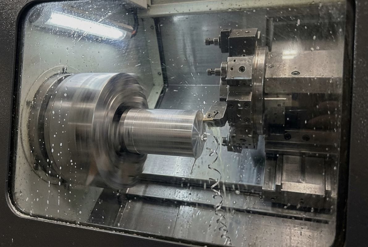
Every week, our Dongguan workshop ships hundreds of CNC turned parts to buyers who needed them yesterday — and the number one question we still hear is: what exactly is the CNC turning process?
The CNC turning process is a subtractive manufacturing technique in which a CNC lathe machine rotates a workpiece at high speed while a stationary single-point cutting tool removes material, guided by G-code programming, to produce precise cylindrical parts, conical shapes, threads, and contoured profiles with tight tolerances.
Below, I will walk you through how CNC turning works step by step, which materials and designs fit it best, how to hold tolerances in volume production, and what you can do right now to cut costs and lead times on your next turning project.
How do I know if my part design is best suited for the CNC turning process?
A question we field almost daily from product engineers in the US and Europe is whether their part should go on a lathe or a milling center — and the answer often saves them thousands of dollars statistical process control (SPC) 1.
Your part design is best suited for CNC turning when its primary geometry is rotational — cylinders, cones, threads, or circular profiles — because the workpiece rotates on a spindle while a cutting tool shapes it, making turning faster, more accurate, and more cost-effective than CNC milling for these shapes.
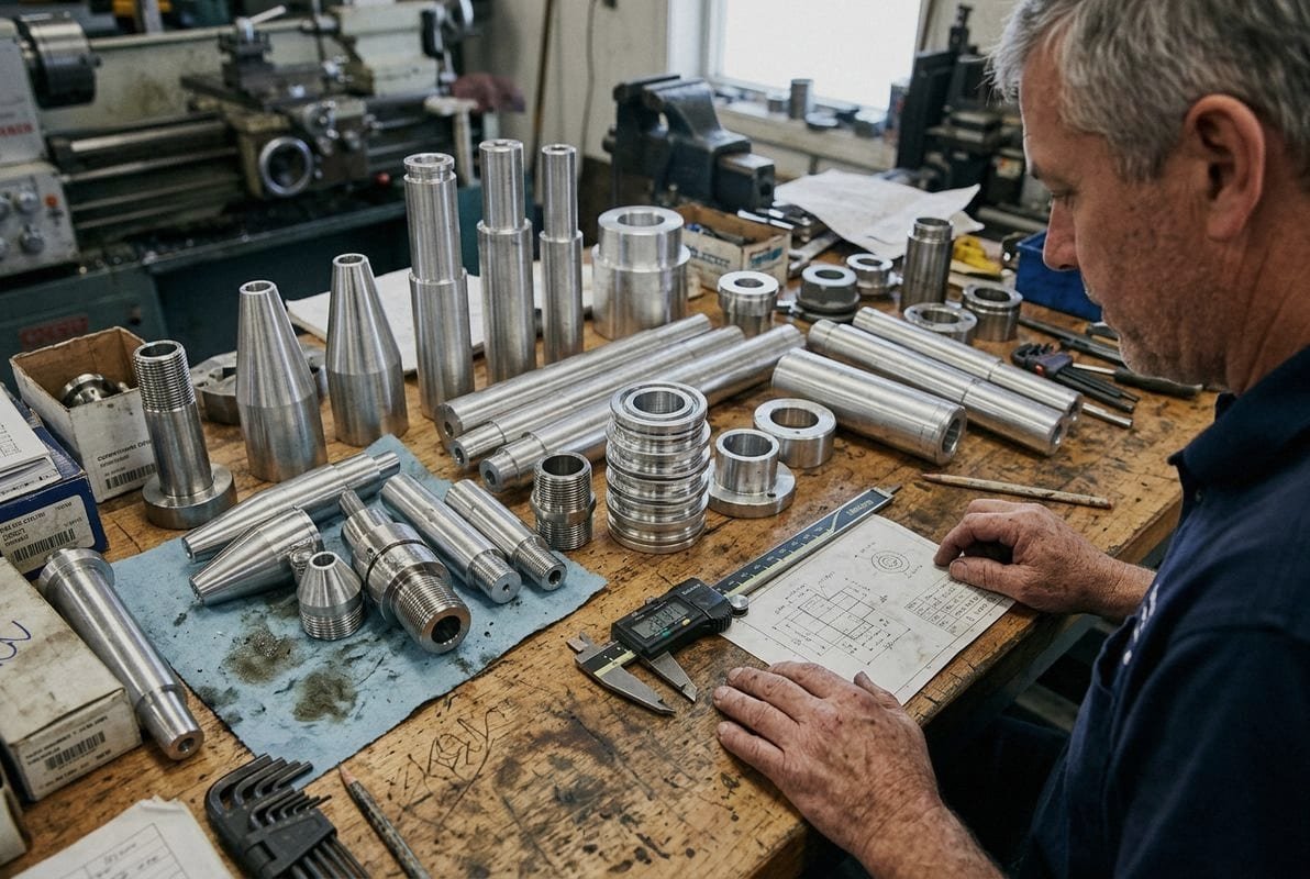
The Rotational Geometry Rule
The simplest test is this: look at your part from the end CAD CAM software 2. If the cross-section is mostly round, CNC turning is probably the right call. Shafts, bushings, couplings, nozzles, threaded fasteners, and impeller hubs are classic turning candidates. Our team processes exactly these kinds of parts every day on 2-axis and multi-axis CNC lathe machine 3s.
When a part has features on multiple sides — pockets, slots, or asymmetric flats — it usually belongs on a milling center. But many real-world parts sit in a grey area. A shaft with a keyway, for example, can be turned first and then milled in a second operation, or handled in one setup on a live-tooling lathe 4.
Quick Decision Checklist
Ask yourself these questions before you send your drawing out for quoting:
| Question | If YES → | If NO → |
|---|---|---|
| Is the main body cylindrical or conical? | Turning is likely the primary process | Consider CNC milling 5 first |
| Does the part need external or internal threads? | Turning handles threads very efficiently | Threads alone don't dictate the process |
| Are most critical tolerances on diameters or bore IDs? | Turning excels at radial precision | Milling may control planar tolerances better |
| Does the part have deep pockets or multi-face features? | A mill-turn center or secondary milling may be needed | Standard turning should work |
| Is the length-to-diameter ratio greater than 8:1? | Turning still works, but a tailstock or steady rest is required | Standard chucking is fine |
Coaxiality — the Hidden Design Requirement
One insight that many engineers overlook is coaxiality 6. Turned parts must guarantee that every diameter shares the same central axis. When I review a customer drawing, I check the coaxiality callout first. If the design stacks multiple bores and outer diameters that must stay concentric within 0.01 mm, a single-setup turning operation on a quality lathe is the most reliable way to achieve it. Moving the part between machines introduces re-clamping error, which hurts coaxiality fast.
Turning vs. Milling at a Glance
| Factor | CNC-svarvning | CNC-fräsning |
|---|---|---|
| Workpiece motion | Rotates on the spindle | Stationary (or indexed) |
| Tool motion | Stationary single-point cutting tool moves in X/Z | Rotating multi-point tool moves in X/Y/Z |
| Best geometry | Cylindrical, conical, threaded | Prismatic, pocketed, multi-face |
| Typical tolerance | ±0.01 mm on diameters | ±0.01 mm on linear dimensions |
| Surface finish | Excellent on OD/ID surfaces | Excellent on flat and contoured faces |
| Cycle time for round parts | Short | Longer (requires indexing) |
If your part matches the turning column, you will save money and time. If it needs features from both columns, ask your supplier about mill-turn capability — our live-tooling lathes combine both processes in a single setup. For a deeper comparison, see our guide on the key differences between CNC milling and CNC turning.
What materials can I select for my high-precision CNC turned components?
Last month, a medical-device buyer in Germany asked us to turn a prototype from PEEK — a high-performance polymer — and the material choice drove the entire tooling and parameter strategy for the job.
You can select from a wide range of workpiece materials for CNC turned components, including aluminum alloys (6061, 7075), stainless steels (304, 316), carbon steel, brass, copper, titanium, alloy steel, tool steel, and engineering plastics such as POM, PEEK, nylon, ABS, and PPSU, each offering distinct strength, corrosion resistance, and machinability characteristics.
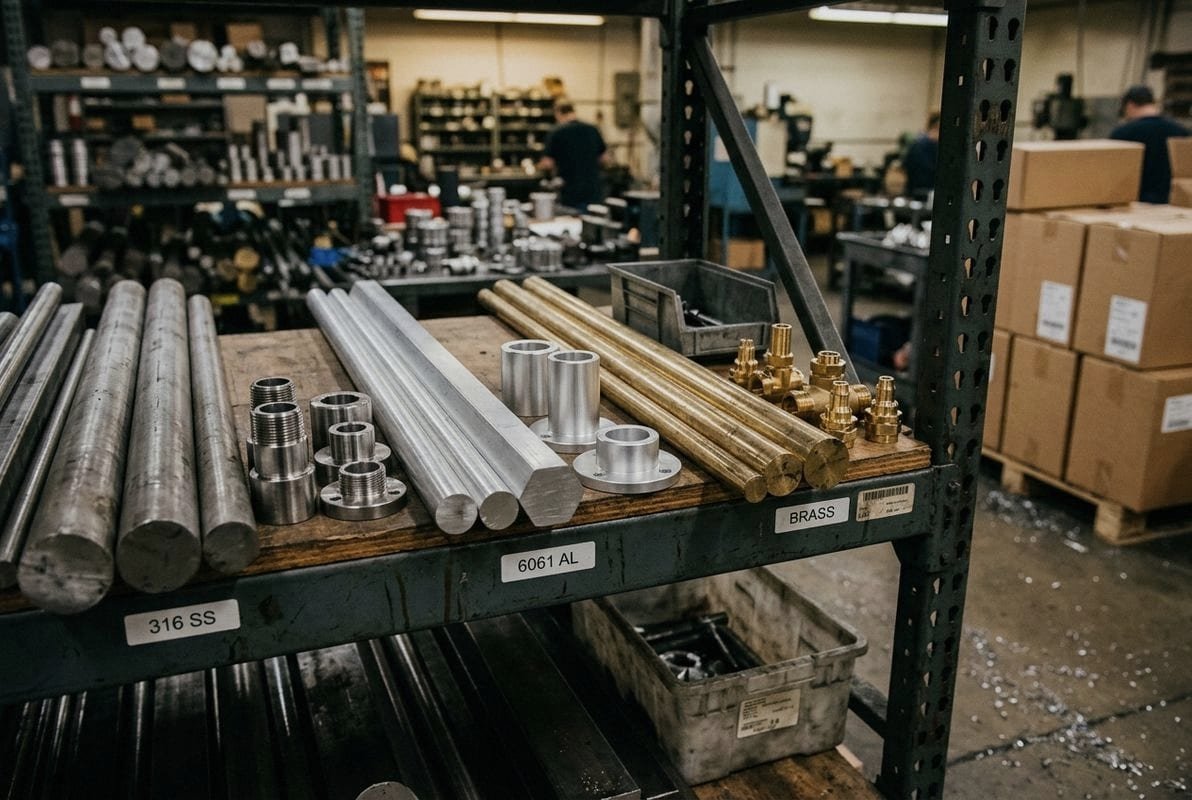
Why Material Choice Matters in Turning
Material dictates every downstream decision: spindle speed, feed rate, depth of cut, cutting tool grade, coolant type, and achievable surface finish. Choose the wrong material and you pay for it in tool wear, scrap, and missed tolerances. Choose the right one and the part almost machines itself.
The cylindrical stock that goes into a CNC lathe machine is most often round bar. But hex, square, or even cast blanks can be chucked with the right workholding. The critical variable is the material's machinability rating — a relative index of how easily a cutting tool can shear it.
Common Metals for CNC Turning
| Material | Typical Grades | Key Properties | Common Applications |
|---|---|---|---|
| Aluminium | 6061, 7075, 2024 | Lightweight, excellent machinability, good corrosion resistance | Aerospace brackets, heat sinks, impeller hubs, enclosures |
| Rostfritt stål | 303, 304, 316, 17-4 PH | Corrosion resistance, high strength, biocompatibility (316) | Medical instruments, food-processing shafts, marine fittings |
| Carbon steel | 1018, 1045, 4140 | High strength, weldable, cost-effective | Automotive shafts, couplings, machinery pins |
| Mässing | C360 (free-cutting) | Excellent machinability, low friction, conductive | Electrical connectors, valve bodies, decorative fittings |
| Koppar | C110 | High thermal/electrical conductivity | Bus bars, heat exchangers, electrical terminals |
| Titan | Grade 2, Grade 5 (Ti-6Al-4V) | High strength-to-weight ratio, biocompatible | Aerospace fasteners, surgical implants |
| Tool steel | D2, A2, O1 | Extreme hardness after heat treatment | Punches, dies, wear-resistant bushings |
Engineering Plastics
When weight, electrical insulation, or chemical resistance is the priority, plastics enter the picture. Our team frequently turns POM (Delrin) for low-friction bushings, PEEK for medical and semiconductor parts, and nylon for wear components. Plastics require sharp tooling, lower spindle speeds, and careful chip evacuation to prevent melting.
How We Match Material to Your Application
When a customer sends us a drawing, we look at the operating environment first. Will the part see salt spray? We suggest 316 stainless. Does it need to be lightweight and anodized? 6061 aluminum with a matte silver finish is our go-to. Is the part a high-RPM impeller that must balance strength with weight? 7075 aluminum or titanium may be the answer.
We also provide material certificates with every shipment. This gives procurement managers — especially those in aerospace and medical — the traceability they need for internal acceptance and regulatory compliance.
How can I ensure my tight tolerances are maintained during mass production turning?
One lesson our quality team learned early — and still reminds every new CNC operator about — is that a perfect first-article sample means nothing if the 5,000th part drifts out of spec.
To maintain tight tolerances during mass production turning, implement statistical process control (SPC), use in-process gauging, schedule regular tool-wear offsets, control workpiece material consistency, stabilize machine temperature, and perform first-article and periodic inspections with documented dimensional reports throughout the production run.

Understanding Why Tolerances Drift
In a single-part scenario, achieving ±0.01 mm on a CNC lathe machine is straightforward. You set the tool offset, run a test cut, measure, adjust, and go. But in a 10,000-piece run, variables accumulate. The cutting tool wears. The spindle heats up and grows thermally. Coolant concentration changes. Bar stock from a new lot may have slightly different hardness. Each factor nudges the dimension a few microns. Over hours, those microns add up.
Our Process for Holding Tolerance at Volume
Here is the sequence we follow in our Dongguan facility, refined over 20 years of precision machining for demanding export markets:
- First-article inspection (FAI): We machine three to five pieces, measure every critical dimension on a CMM 7, and issue an FAI report before the run begins.
- In-process SPC: Operators measure key diameters every 20–50 pieces using calibrated micrometers and bore gauges. Data goes into an SPC chart. If a measurement trends toward the control limit, the operator adjusts the tool offset before the part goes out of tolerance.
- Automated tool-wear compensation: Our CNC controllers can apply incremental offset adjustments based on programmed intervals, pre-emptively compensating for predictable wear.
- Thermal stabilization: We warm up the spindle for 15–20 minutes before production and maintain shop-floor temperature within ±2 °C. This keeps spindle speed and axis positioning consistent.
- Material lot verification: We check hardness and dimensions of incoming bar stock. A harder lot means faster tool wear, so we adjust parameters proactively.
- Final inspection: Before packing, our QC team draws a random sample per AQL standards, measures all critical features, and generates a dimensional inspection report that ships with the order.
Critical Cutting Parameters That Affect Tolerance
| Parameter | Effect on Tolerance | Control Strategy |
|---|---|---|
| Spindle speed (RPM) | Too high → heat buildup → thermal expansion | Match RPM to material; monitor temperature |
| Feed rate | Too aggressive → deflection, chatter → dimensional error | Use manufacturer-recommended feed per rev |
| Depth of cut | Heavy cuts → tool deflection → oversize/undersize | Take a light finishing pass (0.05–0.15 mm) |
| Coolant flow | Inconsistent cooling → thermal variation | Use flood coolant at steady pressure |
| Tool condition | Worn edge → increased cutting force → drift | Replace or re-index inserts on schedule |
The Role of CAD CAM Software
G-code programming 8 generated from CAD CAM software is only as good as the simulation that validates it. Before any production run, we simulate the toolpath to check for collisions, verify radii, and confirm that the finish pass leaves the correct stock allowance. This step catches errors that would otherwise surface as scrap on the shop floor.
What can I do to optimize my drawings for faster lead times and lower turning costs?
A conversation with a US automotive buyer last quarter drove this point home: his original drawing called out tolerances tighter than the part actually needed, and relaxing just two dimensions saved him 20% on per-piece cost.
To optimize drawings for faster lead times and lower turning costs, specify only the tolerances that are functionally necessary, avoid unnecessary surface finishes, use standard tool-accessible features, provide clear GD&T callouts, and include a 3D model alongside your 2D drawing so your supplier can begin CAM programming immediately.
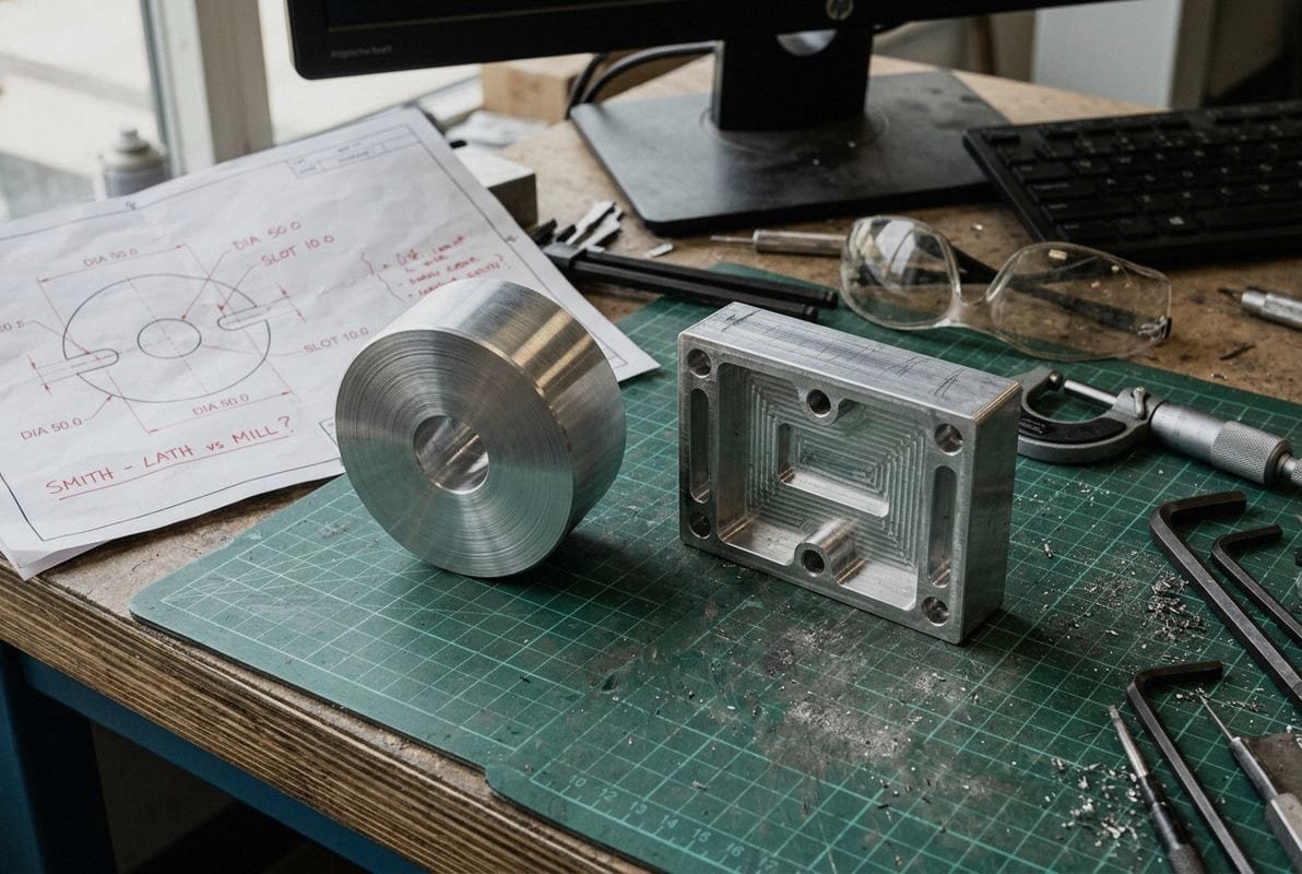
Start With Tolerances
The single biggest cost driver in CNC turning is tolerance. Holding ±0.05 mm is routine and fast. Holding ±0.01 mm requires a finish pass, slower feed, and extra inspection time. Holding ±0.005 mm may demand grinding or a controlled-environment measurement step. Every tighter callout adds cycle time.
Our DFM (Design for Manufacturing) feedback process flags these issues before quoting. When we receive your drawing, our engineers review every tolerance and ask: does this dimension truly need to be this tight? If the answer is no, we suggest relaxing it. This is not about cutting corners — it is about spending your budget where it matters.
Design-for-Turning Best Practices
Here are practical tips we share with customers:
- Avoid internal sharp corners. Turning tools have a nose radius. A sharp 90° internal corner requires a secondary EDM or broaching operation. Specify a radius of at least 0.5 mm.
- Keep wall thickness reasonable. Thin-walled cylindrical parts deflect under cutting force. If walls must be thin, discuss workholding strategy with your supplier early.
- Use standard thread forms. Custom or non-standard threads need special tooling, which adds lead time. Stick to metric ISO or UNC/UNF threads when possible.
- Minimize setups. Every time the part must be flipped or re-chucked, you add time and risk losing coaxiality. Design features so they can be accessed from one or two setups.
- Provide a 3D STEP file. A 3D model lets us import directly into CAM software, generate toolpaths faster, and run simulation before metal cutting begins. This alone can shave a day off the programming timeline. Learn more about the best CAD file formats for CNC machining projects.
How Drawing Quality Affects Lead Time
| Drawing Element | Good Practice | Poor Practice | Impact on Lead Time |
|---|---|---|---|
| File format | 2D PDF + 3D STEP | Hand sketch or low-res image | Good saves 1–2 days |
| Tolerances | Only critical dims tightly toleranced | ±0.01 mm on every dimension | Good saves machining and inspection time |
| Surface finish callouts | Specified only where needed (e.g., sealing surfaces) | Ra 0.8 µm on all surfaces | Good reduces polishing or extra passes |
| Material specification | Exact grade (e.g., 6061-T6) | "Aluminum" with no grade | Good prevents material sourcing delays |
| GD&T | Clear datums, proper symbols | Ambiguous or missing datums | Good avoids back-and-forth questions |
| Thread callouts | Standard, complete (e.g., M8×1.25-6g) | "M8 thread" with no class or pitch | Good prevents re-quoting |
Leverage DFM Before Production
When we provide DFM feedback, we are not just checking your drawing for errors. We are looking for turning operations that can be combined, features that can be simplified, and workpiece material options that machine faster without sacrificing performance. This collaborative step often reduces per-piece cost by 10–25% and compresses lead times from weeks to as few as five days. For more strategies, see our guide on how to reduce CNC machining costs when sourcing custom parts.
Batch Size and Tooling Strategy
For mass production, we recommend discussing batch release schedules up front. Ordering 10,000 pieces in four releases of 2,500 reduces your inventory risk and lets us optimize tool turret setup once, then repeat it. Raw material can be pre-ordered in bulk at a lower unit cost, and our scheduling team can slot the work into open machine time more efficiently.
Conclusion
The CNC turning process is the most efficient path to high-precision cylindrical parts — and the right supplier partnership turns your design into reliable, repeatable production faster than you expect.
Footnotes
1. Explains a key quality control methodology for monitoring manufacturing processes. ↩︎
2. Replaced unknown HTTP with Wikipedia link. ↩︎
3. Provides a foundational understanding of the primary machine used in the turning process. ↩︎
4. Explains an advanced type of lathe combining turning and milling operations. ↩︎
5. Offers a comparison to another common subtractive manufacturing process. ↩︎
6. Defines a critical geometric tolerance for rotationally symmetric parts. ↩︎
7. Identifies a precise measurement tool used for first-article inspection. ↩︎
8. Explains the fundamental programming language used to control CNC machines. ↩︎
9. Specifies a common file format for exchanging 3D models in engineering. ↩︎

 Svenska
  English
  Italiano
  Français
  日本語
日本語  Deutsch (Sie)
  Español
  Русский
  العربية
  Български
  Čeština
  Dansk
Dansk  Suomi
Suomi  עִבְרִית
  हिन्दी
  Nederlands
  Português
  Română
  Slovenčina
  ไทย
ไทย  Tiếng Việt
  Türkçe
  Slovenščina