CNC machining is a powerful technology that has revolutionized the manufacturing industry. It allows us to create complex parts with incredible precision and speed, making it possible to bring our wildest ideas to life.
However, the success of CNC machining heavily depends on CAD designs. Today we will talk something of CNC design guidelines.
What are CAD Designs for CNC?
CAD designs for CNC(Computer Numerical Control) machining are digital designs that guide equipment to manufacture parts. They include information about the part’s geometry, dimensions, materials, and machining process.
We can save a CAD technical drawing in various formats, such as DWG, DXF, and STP. They are widely used in the manufacturing, architecture, engineering, and construction industries.
Why is the Manufacturability of CNC Design So Important?

The manufacturability of a CAD model is crucial because it determines the efficiency and effectiveness of CNC Machining. A CNC machine is an automated tool that requires specific instructions to operate.
A CAD file must consider various factors crucial for manufacturability, such as material selection, part geometry, tolerances, tool selection, and machining strategy. Here are some reasons why the manufacturability of CAD design is so important:
1. Reduces Manufacturing Time
A CAD file that considers manufacturability factors can significantly reduce the time it takes to manufacture a product. A CNC program can produce parts in less time than traditional machining methods by optimizing the machining process and reducing tool changes.
2. Reduces Manufacturing Costs
Part designs for manufacturability can also reduce CNC machining costs by minimizing material waste and optimizing tool life. A CAD file can also be reused, reducing the time and cost of programming each part.
3. Ensures Quality and Consistency
A well-designed CAD file ensures that each part is produced to the same high standard. By considering factors such as tolerances and tool selection, CNC design can ensure that each piece is manufactured to the required specifications and quality.
4. Enables Complex Designs
A CNC machine can produce complex shapes and designs that are difficult or impossible to manufacture. A well-designed part design can enable the production of highly intricate parts and components.
So it’s so important to improve your design. Here are some tips for CAD designs for CNC machined parts that can help you produce high-quality parts with passion and creativity:
Tips 01-Ensure Adequate Wall Thickness
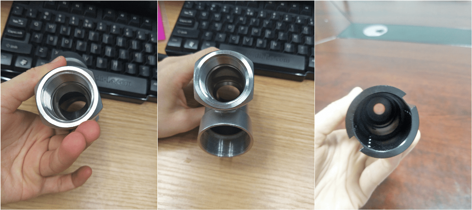
Every detail counts when you design a part for CNC machining. One crucial detail is the parts’ wall thickness. You want your creation to be strong, resilient, lightweight, and efficient. That’s why ensuring adequate wall thickness is essential.
By carefully considering your part’s material, function, and load-bearing requirements and keeping the wall thickness at least 1-2 times the end mill diameter, you can create a masterpiece that looks great and performs flawlessly.
So, pour your heart and soul into your CAD design, and pay attention to every detail, including the thickness of your part walls. Your CNC-machined parts will reflect your passion, creativity, and attention to detail.
In short, considering the safety and reliability of the product, we should avoid using excessively thin walls whenever possible.
Although thin walls may be necessary in some cases, we must recognize their drawbacks and determine the most suitable wall thickness for the product and structure by considering multiple factors.
Here is a chart with the standard minimum thickness for CNC machined parts
| Material | Minimum Wall Thickness |
| Aluminum | 0.020 in (0.5 mm) |
| Brass | 0.030 in (0.75 mm) |
| Copper | 0.030 in (0.75 mm) |
| Steel | 0.040 in (1.0 mm) |
| Stainless Steel | 0.050 in (1.25 mm) |
| Plastics (ABS, Nylon, Polycarbonate, etc.) | 0.030 in (0.75 mm) |
Tips 02-Limit Tolerance Usage to Necessary Cases

Tolerance is essential in engineering and manufacturing, but excessive use can lead to lower quality and higher machining costs. Tight tolerances should only be specified wherever necessary. We must also maintain homogeneous tolerancing to minimize machining time.
For example, a slight deviation may be acceptable within the tolerance limit if the CNC machining process requires a specific diameter for a certain component.
However, if the variation is too significant, it may compromise the performance or safety of the final product, and the part should be rejected. However, the tight tolerances of a simple component will increase its machining cost.
Tips 03-Round Internal Edges with Radii
When you design the internal edges, the sharp internal edges should be rounded with radii to enhance the part’s visual appearance, reducing stress concentrations and making the machining process smoother and safer. This can be done through fillet or chamfer commands in the CAD software.
Also, to prevent excessive wear and tear on cutting tools, it is crucial to incorporate a radius into the internal edges of designs since most cutting tools are cylindrical and unable to machine sharp internal edges.
Adding a radius that is 130% of the milling radius is generally recommended. However, if sharp internal corners are necessary, consider including undercuts in the design instead of reducing the edge radius.
Tips 04-Design the width-to-depth ratio of cavities appropriately
During the design process for CNC machining, we must consider the appropriate width-to-depth ratio to ensure structurally-sound and manufacturable cavities. A high width-to-depth ratio can lead to warping or distortion, while a low ratio can reduce strength and stability.
The ratio should be chosen to achieve the desired performance and aesthetics while ensuring the cavity is structurally sound and manufacturable.
Tips 05-Set a Cap on the Thread Length
When you improve your CAD designs, you can focus on using sufficiently long thread lengths on the tapped holes. A thread longer than three times the hole diameter is unnecessary.
To accommodate blind holes, we recommended incorporating an unthreaded section at the base of the hole. It allows the CNC threading tool to thread the hole completely.
Tips 06-Avoid Too Small Features
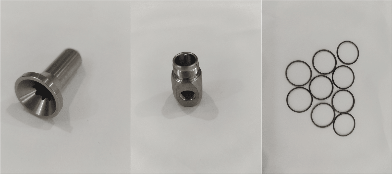
When creating CAD designs for CNC machining, we must consider the manufacturing technology limitations. Using too small features can cause issues such as tool breakage, increased machining time, reduced accuracy, etc.
We also need to consider the CNC machine’s capabilities and cutting tool sizes when we design the CNC machined parts with minimum feature sizes.
The minimum CNC machining tool diameter is 2.5mm, which means that features smaller than this size are challenging to machine accurately. Specialized tools may be required to produce minuscule features, resulting in longer machining times and higher costs.
Hence, it is advisable to avoid designing small features unless they are essential to the part’s functionality.
Tips 07-Eliminate Unnecessary Text and Lettering.

Eliminating unnecessary post machining processes, such as text and lettering can help reduce the part cost:
Keep only the text and lettering that convey critical information.
Remove any unnecessary decorative elements or features
Consider standardized font instead of custom lettering font.
Minimize the amount of text
Avoid excessive depth or detail:
Tips 08-. Avoid Unnecessary Aesthetic Features
When designing products or interfaces, we should avoid unnecessary aesthetic features that can lead to a cluttered and confusing design because these design elements do not add value or functionality.
Here are some tips to avoid excessive redundant aesthetic features:
1. Focus on functionality
2. Please keep it simple.
3. Use visual hierarchy:
4. Use whitespace:
5. Avoid trends:
By following these tips, you can create a product or interface that is both functional and aesthetically pleasing.
Tips 09-Design Holes With Standard Sizes
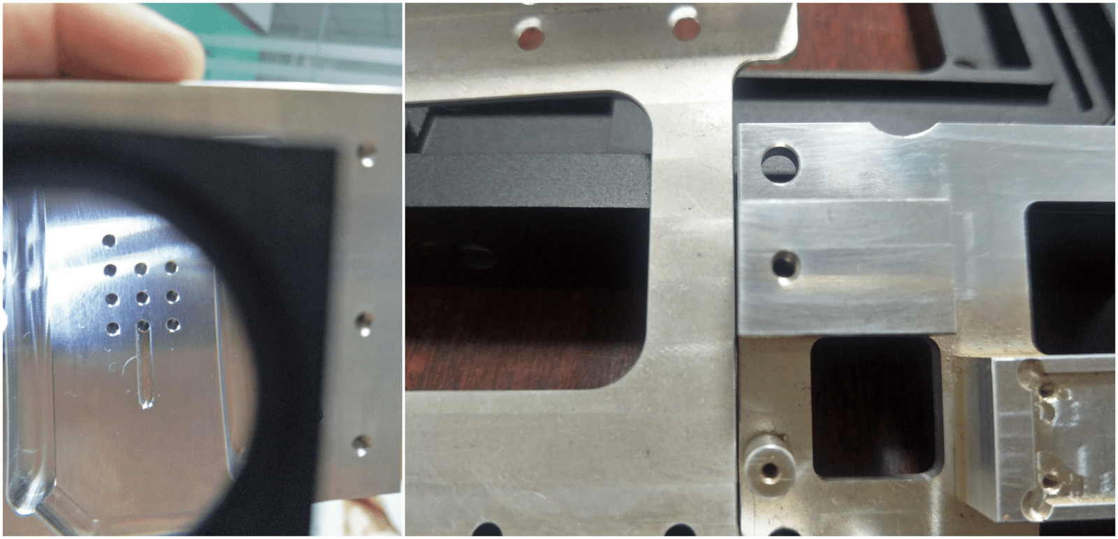
Designing holes with standard sizes is a best practice in engineering and manufacturing. Standard hole sizes, such as those defined by ISO or ANSI standards, are commonly used and readily available in the market. Here are some reasons why designing holes with standard sizes is essential:
Availability of Tools: Ensure standard sizing for holes milled by standard drill bit sizes, which helps save machine time and expenses since holes not designed to standard would call for an end mill tool.
Ease of Assembly: When components have holes with standard sizes, it is easier to align and fit them together during assembly. It helps to reduce assembly time and ensures the pieces fit together correctly.
Consistency and Interchangeability: Designing holes with standard sizes ensures consistency and interchangeability of components. When you design the part with the exact standard hole sizes, they can be easily replaced or interchanged with other similar features, regardless of their origin.
Reduced Cost: Standard hole sizes are usually more cost-effective because you produce them in larger quantities and are readily available in the market. It reduces the cost of purchasing, manufacturing, and inventorying custom tooling.
Improved Design: Designing holes with standard sizes can lead to improved design and functionality of the component. It is because standard sizes have been developed and tested over time to ensure they meet the required specifications.
In conclusion, designing holes with standard sizes is important because it ensures the availability of tools, ease of assembly, consistency, and interchangeability of components, reduced cost, and improved design. Standard hole sizes can result in a more efficient, cost-effective, and reliable manufacturing process.
Tips 10- Consider Part Size

When designing a CNC machined part in a CAD file, considering the appropriate part size is crucial to ensure the final product meets the required specifications. Here are some factors to consider when determining the part size :
1. Functionality: Consider the part’s functionality and determine the size to fulfill its intended purpose. The piece should be large enough to serve its function but not overly large, as this can lead to unnecessary material waste and additional machine costs.
2. Manufacturing capabilities: Consider the manufacturing capabilities of the CNC machines used to produce the part. Ensure that the part size is within the equipment’s capabilities so that we can make it efficiently.
3. Material selection: We need to consider the parts’ material. Different materials have different properties, which can affect the size and shape of the piece.
4. Tolerance requirements: Consider the tolerance requirements for the part. We must design the piece to meet the required tolerances, ensuring we can produce it within acceptable limits.
5. Assembly requirements: Consider the assembly requirements for the part. We optimize the part size to facilitate assembly, minimize the number of components, and ensure that it fits together correctly.
6. Shipping and handling: Consider the part size for shipping and handling purposes. Ensure it is small enough to be shipped and handled easily but not so small that it can’t fulfill its intended purpose.
The author’s words:
Here we have learned the most common key points of CAD design. I will be happy if it’s helpful to your design work. We will describe some of these tips in detail in the following articles. Welcome to our blog to get our latest information.
You can also send the drawings to us for DFM evaluation to ensure the machinability of your products at the design stage. See what our friends love to do!
