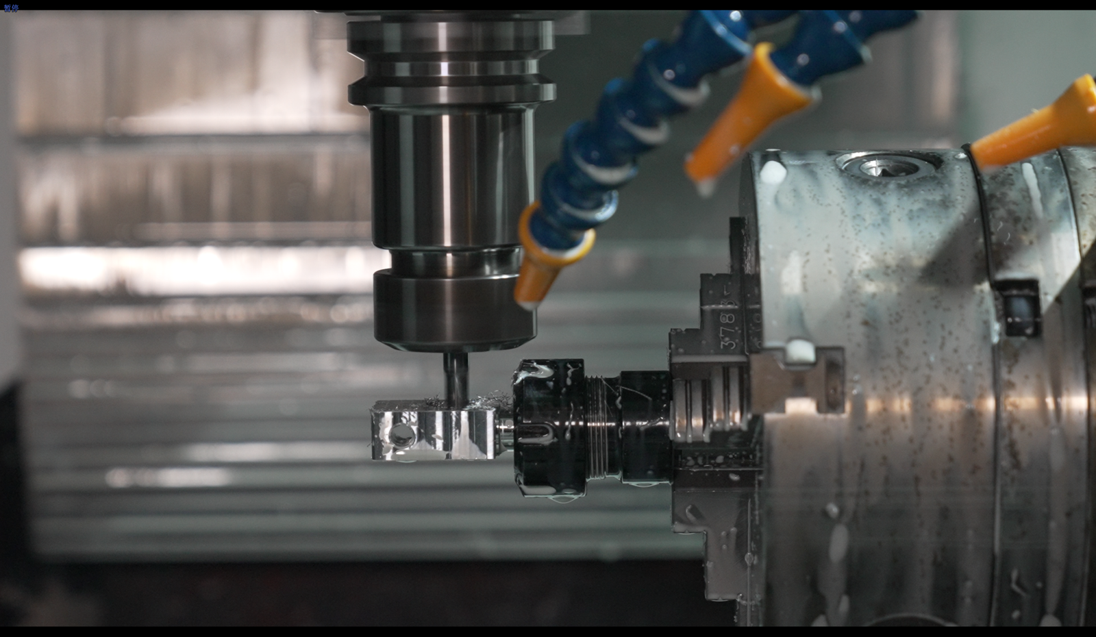
When you work as an equipment manufacturer and require outsourcing of components for your equipment, it is common to rely on machine shops. They specialize in carefully managing the entire process, from the procurement of raw materials through production and up to quality control. They aim to meet your specific needs for equipment accessories.
As a process builder in a machining factory, you create programming processes for drawings, considering every step of the production process. Precision machining typically involves various methods, such as drilling, milling, grinding, laser, and electrical discharge machining (EDM). These machining techniques can be further categorized as either CNC machining processes or manual, depending on the design requirements of the drawings.
In this article, you will learn all these common machining processes and how we can take advantage of these processes.
What is Machining?
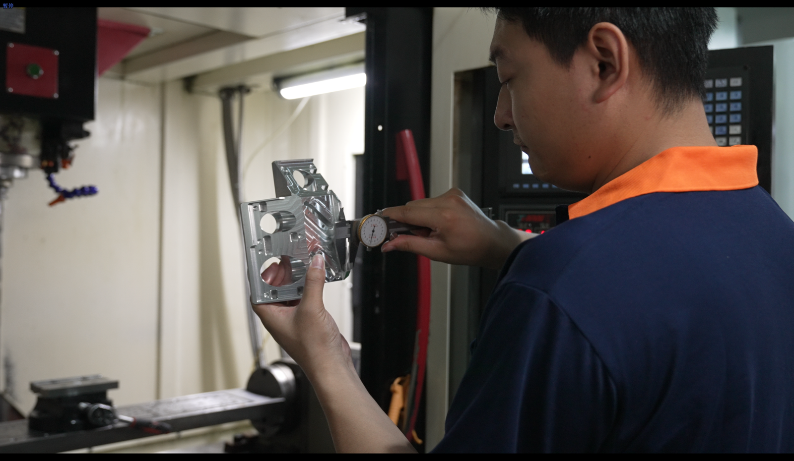
Machining is a manufacturing process that removes material from a workpiece to shape it into a desired form. Techniques like turning, milling, drilling, grinding, and EDM achieve specific shapes, sizes, and surface finishes. It is performed manually or with a CNC machine, allowing for precise and automated operations. Machining is crucial in various industries for creating custom parts with specific dimensions and characteristics.
What Processes Will the Machined Parts Involve?
Here is a simplified process flow for machining a part:
1. Design the part using CAD software.
2. Select the appropriate material for the part.
3. Prepare the material by cutting it into the desired size and shape using tools like saws, shears, or laser cutting machines.
4. Create a CNC program using CAM software, specifying the machining operations and parameters, which includes the necessary toolpaths, cutting parameters, and machining sequences.
5. Set up the workpiece securely in the machine using clamps or fixtures.
6. Perform turning operations using a lathe machine if needed. This process removes material from the workpiece and creates cylindrical shapes, such as outer or inner diameters, tapers, or grooves.
7. Perform operations like face milling, slot milling, contour milling, or pocket milling as required. Use milling tools like end mills or face mills to remove material and create various workpiece shapes, features, or profiles.
8. Drill holes in the workpiece using a drilling machine or CNC machining center. Select appropriate drill bits based on the desired hole size and type (through-hole or blind-hole).
9. Perform grinding operations if needed, using a grinding machine to achieve tight tolerances, precise dimensions, and improved surface finishes.
10. Use specialized boring tools to enlarge or refine existing holes.
11. Inspect the machined part using measuring tools like calipers and micrometers.
12. Perform any necessary finishing processes, such as polishing or deburring.
13. Conduct a final inspection to ensure the part meets specifications.
14. If required, apply coatings or surface treatments.
15. Package and deliver the finished part.
Please note that the actual Process may involve additional steps or variations based on the specific requirements of the part and the machining facility.
What are Common Machining Processes?
1. Turning

What is Turning?
Turning is a machining process that removes the material from a rotating workpiece to create cylindrical shapes or achieve specific geometries. It is performed on a lathe machine using a cutting tool that removes material as the workpiece rotates.
The Entire Process of Performing Turning
Turning creates cylindrical shapes or removes material from a workpiece’s outer diameter (OD) or inner diameter (ID). Here are the details of the turning process:
Mount the workpiece: Securely mount the workpiece onto the spindle of a lathe machine, ensuring proper alignment and stability.
Select cutting tools: Choose an appropriate cutting tool based on the material, desired shape, and surface finish. Common turning tools include turning inserts, boring bars, and threading tools.
Set cutting parameters: Determine the cutting speed, feed rate, and depth of cut based on the material properties and desired surface finish. These parameters influence the material removal rate and the quality of the finished surface.
Start the lathe machine: Turn on the lathe machine, ensuring the spindle rotation is in the correct direction for the desired cutting direction (either toward or away from the operator).
Rough turning: Perform roughing cuts to remove excess material from the workpiece, approaching the desired dimensions. This is done using heavier cuts and higher feed rates to remove material quickly.
Finish turning: Once the workpiece is close to the desired dimensions, switch to finer cutting tools and reduce the feed rate. Take light passes to achieve the final dimensions and improve the surface finish.
OD turning: If machining the outer diameter, move the cutting tool along the length of the workpiece while it rotates. Adjust the tool position and cutting depth to shape the OD according to the design specifications.
ID turning: If machining the inner diameter, use a boring bar or specialized tool to remove material from the inside of the workpiece. Adjust the tool position and cutting depth to achieve the desired ID dimensions and surface finish.
Facing: Perform facing cuts to create a flat surface perpendicular to the rotational axis. This is often done at the ends of the workpiece to achieve a smooth, perpendicular surface.
Chamfering and threading: Use appropriate tools to create chamfers or thread profiles on the workpiece if required. Chamfers provide a beveled edge while threading creates internal or external threads.
Continuous monitoring: Continuously monitor the cutting process, checking for tool wear, chip formation, and surface quality. Adjust as needed to maintain dimensional accuracy and achieve the desired surface finish.
Coolant and lubrication: Depending on the material and cutting conditions, apply coolant or cutting fluid to the cutting zone to dissipate heat, improve chip evacuation, and prolong tool life.
Final inspection: After turning, perform a dimensional inspection of the turned part using measuring tools like calipers or micrometers. Verify that the dimensions, tolerances, and surface finish meet the required specifications.
It’s important to note that the specific steps and parameters may vary depending on the part’s complexity, the material being machined, and the lathe machine’s capabilities.
2. Milling
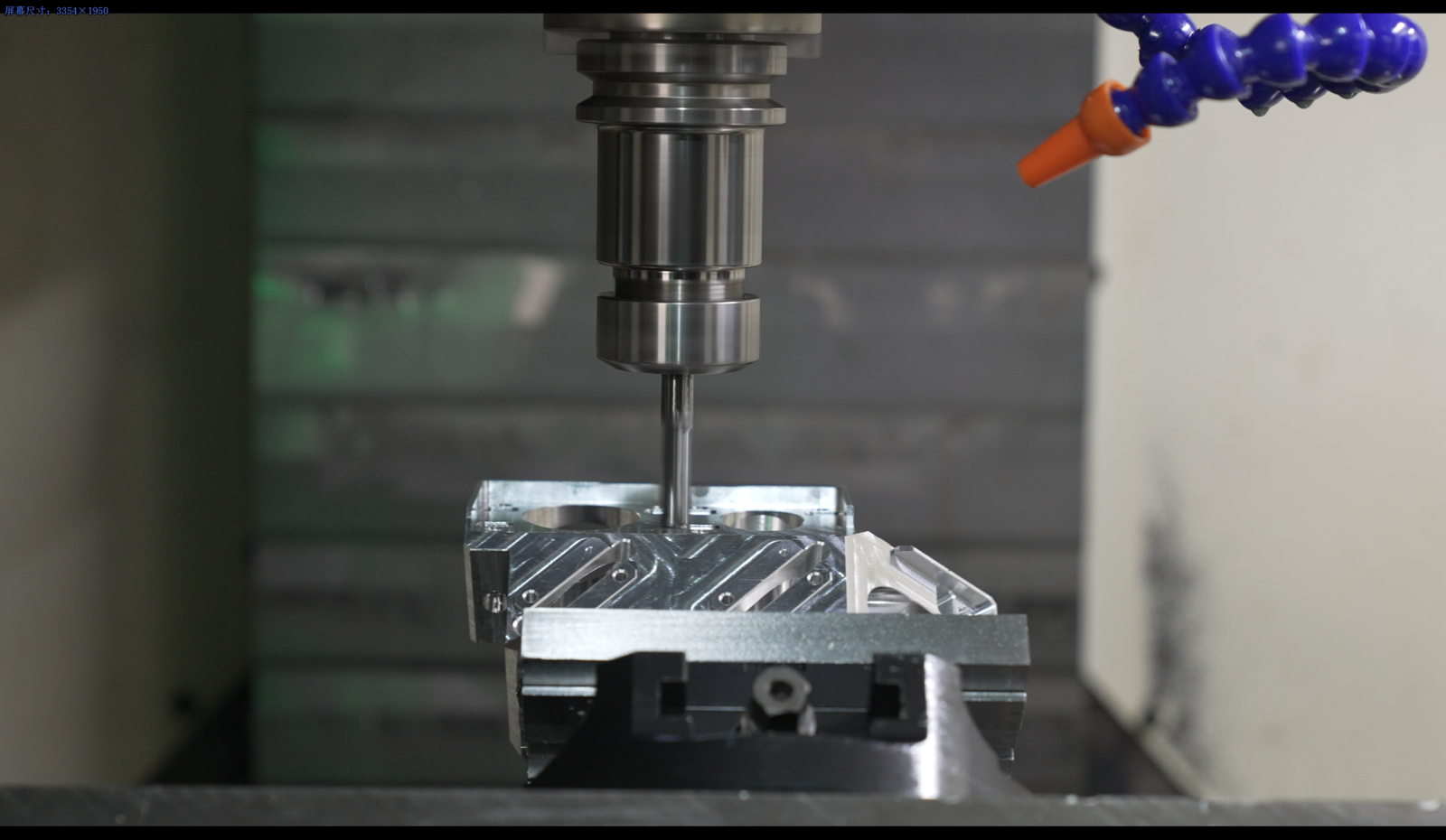
What is Milling?
Milling is a machining process where rotating cutting tools remove material from a stationary workpiece. It’s done on milling machines and can involve cutting the workpiece’s face, creating slots or grooves, machining complex shapes, and drilling holes. Milling machines come in different types, and CNC milling machines use computers to control the process precisely. Milling is commonly used in manufacturing to create intricate components and achieve precise shapes on various materials.
CNC Milling VS Non-Automatic Milling

CNC Milling Operations and How to Control Quality
Programming: Double-check the CNC program for accuracy, ensuring the toolpaths, cutting parameters, and coordinates are correctly defined. Simulate the program using CAM software to identify any potential collisions or errors.
Workpiece Setup: Ensure proper alignment and fixation of the workpiece on the milling machine’s worktable or fixture. Use precision measuring tools to verify the workpiece position and alignment.
Tool Selection: Choose high-quality cutting tools suitable for the material and machining requirements. Check the condition of the tools, including sharpness, integrity, and appropriate tool coatings.
Machine Setup: Follow the manufacturer’s instructions, including inputting the correct workpiece and tool offsets, aligning the machine components, and verifying clearances.
CNC Program Loading: Verify that the correct programs are loaded into the machine’s control unit. Double-check the program for any errors or discrepancies.
Machine Calibration: Perform regular calibration to ensure accurate tool length offsets and positioning. Use calibrated measuring instruments to verify the machine’s accuracy.
Machine Warm-Up: Allow the machine to warm up adequately before starting the milling process. Monitor the machine’s normal vibrations or noises.
Machining: Monitor the machining process for proper chip evacuation, coolant flow, and tool performance. Check for any deviations from the programmed toolpaths or unexpected issues.
Monitoring: Continuously monitor the milling process, including observing the cutting tool’s condition, chip formation, and coolant effectiveness. Make adjustments if necessary to maintain the desired quality.
Finishing Operations: Pay attention to finishing operations such as facing, chamfering, or hole drilling, ensuring proper tool selection and technique. Monitor the surface finish and dimensions during these operations.
Inspection: Conduct regular inspections using calibrated measuring instruments to verify dimensions, tolerances, and surface finish. Perform spot checks throughout the process to ensure consistency.
Post-Processing: Ensure that any required post-processing steps, such as deburring or surface treatment, are performed with care and attention to detail.
Part Removal: Handle the machined parts carefully during removal to avoid damage or scratches. Inspect the final part after removal to ensure it meets the required specifications.
Throughout the CNC milling process, document the key parameters, measurements, and observations to enable traceability and facilitate troubleshooting if any issues arise. Implement quality control measures, including regular maintenance of the milling machine and cutting tools, to ensure consistent and reliable performance.
3. Drilling
What is Drilling?
Drilling is a machining process that creates holes in solid materials by removing material with a rotating cutting tool called a drill bit. The drill bit is pressed against the workpiece and rotated at high speeds while axial force is applied to penetrate the material and form a hole. Drilling is a common operation performed in various industries, such as manufacturing, construction, metalworking, woodworking, and maintenance.
Here are some key aspects of the drilling process:
1. Drill Bits: Drill bits come in different sizes, shapes, and materials to suit specific drilling requirements. Common types include twist drills, center drills, spade drills, step drills, and hole saws.
2. Drilling Machines: Drilling is typically performed using drilling tools, such as drill presses, handheld drills, or specialized drilling equipment. These machines provide stability and control during the drilling process.
3. Workpiece Setup: The workpiece is securely placed using clamps, vises, or fixtures to ensure stability and prevent movement during drilling.
4. Speed and Feed Rate: The drilling speed and feed rate depending on the material being drilled and the size of the drill bit. Proper speeds and feeds help ensure efficient material removal and prevent overheating or tool damage.
5. Coolant or Cutting Fluid: For certain materials or drilling operations, coolant or cutting fluid may be used to lubricate and cool the drill bit, prolonging its life and improving the quality of the hole.
6. Drilling Techniques: Different drilling techniques can be employed based on the requirements. These include through drilling (creating a hole that passes completely through the workpiece), blind drilling (creating a hole that does not pass through), and countersinking (enlarging the entrance of the hole to accommodate screw heads).
7. Depth Control: Depth control mechanisms, such as depth stops or collars, ensure consistent hole depths and prevent over-drilling.
8. Chip Removal: Chips (swarf) are generated during drilling. Proper chip removal is essential to maintain cutting efficiency and prevent chip clogging. This can be achieved using chip flutes on the drill bit or applying cutting fluid.
9. Hole Quality Inspection: After drilling, the quality of the hole can be inspected using measurement tools such as calipers or depth gauges to verify dimensions, roundness, and surface finish.
Drilling is a versatile process for creating holes of various sizes and depths in various materials, including metals, plastics, wood, and composites. It is crucial to follow safety guidelines, select the appropriate drill bit and machine for the material, and adhere to proper drilling techniques to ensure accurate and efficient hole production.
3. Grinding
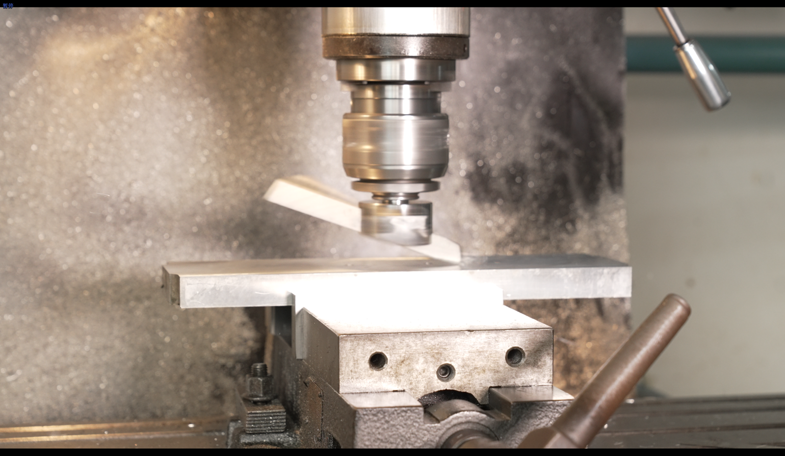
What is Grinding?
Grinding is a mechanical machining process that uses the frictional action of abrasive grains on a grinding wheel surface to remove material from the workpiece surface to achieve the desired size and shape.
The Usage of Grinding
The grinding process for machined parts is used for surface finishing, dimensional accuracy, deburring, grinding of hardened materials, shaping complex shapes, thread grinding, surface modification, and tool and die sharpening.
Grinding Process on a Machine
1. Machine setup: Ensure the grinding machine is properly set up and ready for operation. This includes verifying the machine is securely anchored, checking the alignment of the grinding wheel or tool, and adjusting any necessary machine settings.
2. Workpiece preparation: Clean the workpiece to remove any contaminants or debris affecting the grinding process. Securely fasten the workpiece to the machine using clamps, fixtures, or other appropriate methods.
3. Wheel selection: Choose the right grinding wheel for the specific application. Consider the workpiece material, required surface finish, and desired material removal rate. Install the selected grinding wheel onto the machine according to the manufacturer’s instructions.
4. Machine parameter adjustment: Set the grinding parameters on the machine to achieve the desired outcome. This includes adjusting the machine controls for parameters such as wheel speed, feed rate, depth of cut, and coolant flow rate. Refer to the machine manual for guidance on adjusting these parameters.
5. Start the machine: Power on the grinding machine and bring it to the operating speed specified by the manufacturer. Ensure that all safety precautions are followed, such as wearing appropriate personal protective equipment (PPE) and keeping hands clear of rotating parts.
6. Grinding operation: Move the workpiece or the grinding wheel/tool along the desired path or pattern to perform the grinding operation. Maintain a consistent feed rate and avoid excessive pressure or overheating. Monitor the grinding process for any abnormalities or issues.
7. Coolant application: If required, apply coolant or cutting fluid to the grinding zone to aid in cooling and lubrication. The coolant helps prevent excessive heat buildup and removes swarf or debris from the grinding area.
8. Completion and inspection: Once the grinding operation is complete, stop the machine and carefully remove the workpiece. Inspect the workpiece for the desired surface finish, dimensions, and quality criteria. Use appropriate measuring tools to ensure accuracy.
9. Machine maintenance: Clean the machine and remove any grinding residue or debris. Check the condition of the grinding wheel and replace it if necessary. Perform routine maintenance tasks as the machine manufacturer recommends to keep the machine in good working condition.
Remember, these steps provide a general overview of the grinding Process on a machine, but specific procedures may vary depending on the machine type, application, and manufacturer guidelines. Always refer to the machine manual and follow safety precautions for a successful and safe grinding operation.
4. EDM Machining
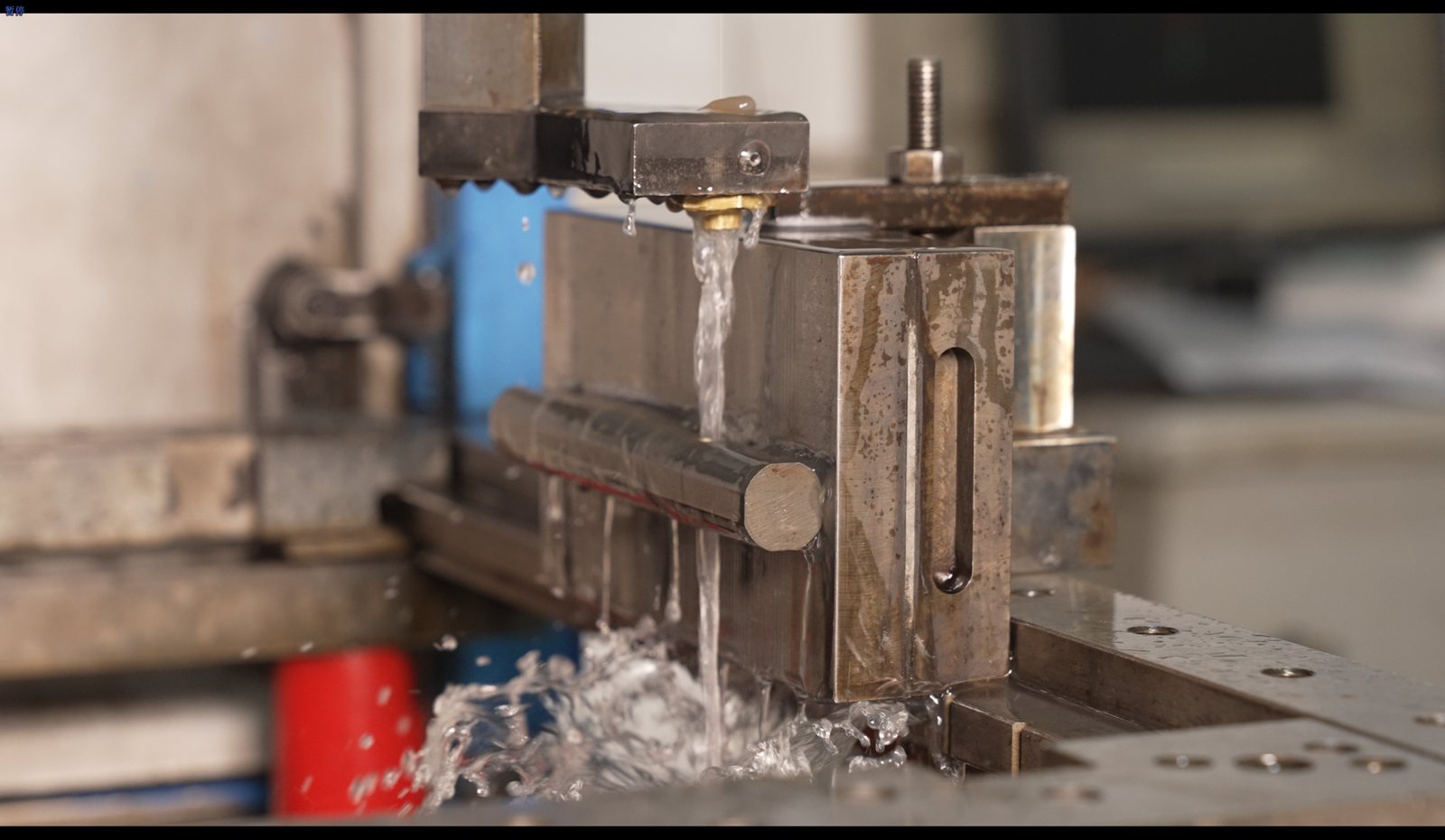
EDM (Electrical Discharge Machining) is a precision machining process that utilizes electrical discharges or sparks to remove material from a workpiece.
EDM machining is known for its ability to work with extremely hard materials and intricate shapes that are difficult to machine using conventional methods. It is commonly used in aerospace, mold and die-making, and precision manufacturing. EDM can achieve high levels of precision, but the process can be slower than traditional machining techniques.
Here’s an overview of the EDM machining process:
1. Machine setup: Set up the EDM machine, ensuring it is properly calibrated and aligned. Secure the workpiece in the machine’s work-holding system.
2. Electrode selection: Choose the appropriate electrode material and shape based on the desired machining characteristics and the material being worked on. The electrode can be a wire or a shaped tool made of conductive material, usually copper or graphite.
3. Dielectric fluid: Fill the machine’s tank with a dielectric fluid, an electrical insulator, and coolant during machining. The dielectric fluid also helps flush away eroded material and maintain stable machining conditions.
4. Program generation: Create or load a computer numerical control (CNC) program that defines the desired machining path and other parameters. This program guides the movement of the electrode and controls the electrical discharges.
5. Initial positioning: Position the electrode close to the workpiece without making contact. Fine-tune the alignment and positioning to ensure proper engagement and accurate machining.
6. Electrical discharge: Apply a high-frequency electrical voltage between the electrode and the workpiece. As the voltage is applied, electrical discharges or sparks occur, rapidly heating and vaporizing the material at the contact point.
7. Material removal: The electrical discharges cause small craters or indentations in the workpiece, removing material layer by layer. The dielectric fluid helps carry away the eroded material and cools the workpiece.
8. Control and monitoring: Throughout the machining process, the machine’s CNC system controls various parameters such as discharge frequency, current, pulse duration, and servo movements. This ensures precise control and accuracy during material removal.
9. Finishing and cleaning: After the EDM machining, carefully remove the workpiece from the machine. Perform any necessary post-processing steps such as deburring, cleaning, or surface treatment to achieve the desired result.
How to Decide the Machining Processes of a Machined Part?

Here are some examples of processes with different details in the drawings.
Holes:
Blind holes: Drilling processes, whether using CNC Machining Process or non-automatic methods, can create blind holes of various diameters and depths.
Through holes: Drilling processes can also create holes that pass completely through the workpiece.
Counterbored holes: For counterbored holes, CNC milling can be used to create the larger diameter opening while drilling creates the central hole.
Countersunk holes: Similar to counterbored spots, milling can create a larger opening while drilling forms the countersunk feature.
Slots and contours:
Straight slots: Non-automatic machining processes such as manual milling or shaping can create linear spaces by guiding the workpiece against the cutting tool or using a slotting attachment.
Complex contours: CNC milling processes excel at machining complex contours and shapes by following precise toolpaths generated from the design.
Internal features: EDM machining can erode the material and create desired internal slots or undercut characteristics.
Surface features:
Surface finishes: CNC milling processes can select cutting tools, toolpaths, and feeds and speeds to achieve a wide range of surface finishes, from rough to mirror-like smoothness.
Textures or patterns: CNC milling can be used with specialized tooling, such as engraving bits or form cutters, to create textured or patterned surfaces based on the design specifications.
Complex shapes:
3D geometries: CNC milling is highly capable of machining complex 3D shapes and intricate geometries using multi-axis machines. The design can be translated into toolpaths, allowing the machine to sculpt the desired shape precisely.
Simple shapes: Using standard cutting tools and operator expertise, non-automatic machining processes like manual milling or turning can create simpler forms such as cylinders, cubes, or prisms.
Material considerations:
Material hardness: For hard materials like hardened steel, carbide, or ceramics, EDM machining processes, such as wire EDM or sinker EDM, are effective at eroding the fabric using electrical discharges.
Material sensitivity: Some materials may be prone to heat damage or deformation. Choosing machining processes with low heat generation, such as high-speed or non-automatic methods with appropriate cutting conditions, can help minimize the risk of material damage.
Considering these additional details and their applicability to specific drawing design features, you can determine the most suitable machining processes to accurately and efficiently create the desired part.
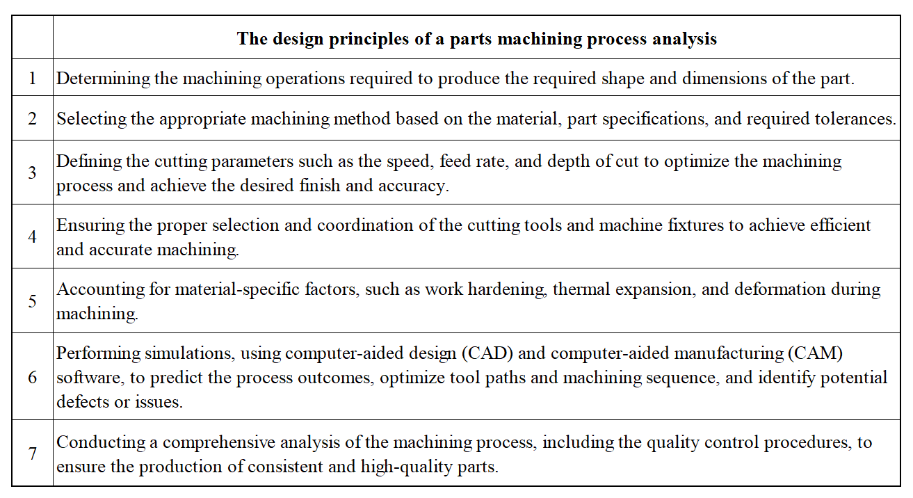
What are the Design Principles of the Parts Machining Process Analysis?
The design principles of the parts processing process analysis are shown in the table below.
What Main Factors Can Easily Cause Deformation of the Workpiece in Machining?
Heat Generation
The heat generated during the machining process can cause thermal expansion, leading to the workpiece’s deformation.
Cutting Forces
Cutting forces generated during the machining process can cause bending and twisting of the workpiece, especially when using long and slender workpieces or when machining thin walls.
Improper Fixturing
Improper workpiece fixturing can cause misalignment and uneven loading, leading to the deformation of the workpiece.
Material Properties
The material properties of the workpiece, such as the modulus of elasticity and yield strength, can affect its susceptibility to deformation during machining operations.
Tool Wear
Tool wear during the machining process can cause changes in cutting forces, leading to the deformation of the workpiece.
Inefficient Chip Evacuation
Poor chip evacuation in machining can cause pressure buildup on the workpiece, resulting in deformation.
Improper Machining Parameters
Improper selection of machining parameters, such as cutting speed, feed rate, and depth of cut, can cause excessive material removal or generate excessive heat leading to deformation.
How to Improve the Quality of Machined Workpieces?
Use High-Quality Materials
Choose materials suitable for the machining process and other materials of high quality.
Optimize the Machining Process
To achieve the desired results, ensure the selection of the right machining parameters, such as cutting speed, feed rate, lubrication, and tool geometry.
Maintain and Calibrate Equipment
Regular maintenance and calibration of the machines and tools will help maintain consistent and accurate results.
Implement Advanced Quality Control Techniques
Use advanced quality control techniques such as statistical process control (SPC), computer-aided inspection (CAI), and coordinate measuring machines (CMM) to verify the accuracy of the machined workpieces.
Train Machine Operators
Ensure that the machine shop operators are well-trained in using the machine and its parameters to maximize the machining results.
Use CAD and CAM Software
Use computer-aided design (CAD) and manufacturing (CAM) software to optimize the design and machining process and other processes, including tool paths and selection.
Employ Post-Processing Techniques
Employ other post-processing techniques, such as heat treatments and coatings, to improve machined workpieces’ mechanical properties and surface finish.
Conclusion
In this article, we have learned common Machining Methods like milling, turning, grinding, drilling, and EDM. However, how to choose the correct manufacturing processes and issue a proper and high-efficient process flow will depend on your part designs. In special cases, you will need to consult the high-skilled technicians. Welcome to contact STCNC for any issues you met during the production. And welcome to outsource machining tasks to our factory.
