
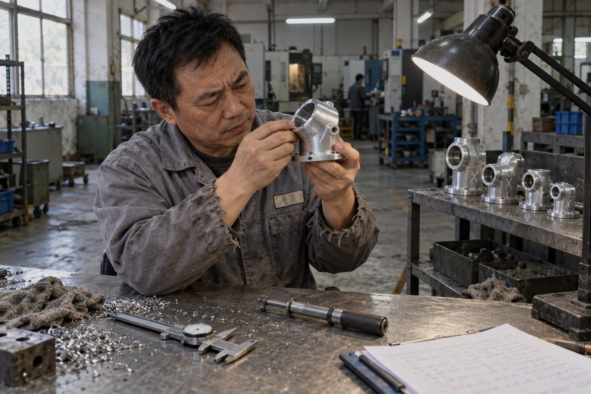
A gripper housing once failed our final check because one bearing bore sat 0.03 mm off. Choosing CNC machining for robotics components wisely prevents that kind of surprise.
Choose CNC machining for robotics components by starting with function: identify load paths, bearing fits, and datums, then match geometry to milling or turning, pick aluminum, steel, or titanium by strength-to-weight needs, tolerance only critical features, and qualify a supplier on inspection, DFM, and repeatable batch quality.
That sounds simple. In practice, most sourcing problems come from skipping one of those steps. Below, I walk through the four questions buyers ask us most often, and the answers we give from our own shop floor in Dongguan.
How do I evaluate a CNC supplier’s precision capabilities for robotics components?
Our inspection room keeps a small shelf of parts we rejected. Most are joint housings where a bearing bore drifted after a second setup.
Evaluate a CNC supplier's precision by asking which tolerances they hold consistently, not occasionally; requesting first-article inspection reports from CMM or bore gauges; confirming critical datums are machined in one setup; checking 5-axis and turning capability; and verifying ISO 9001 quality systems and material traceability.

Start with function, not the machine
Not every surface on a robot part needs the same precision tolerances. Before we quote a joint housing or a custom actuator body, we sort its features into four groups: load-bearing surfaces, motion and wear surfaces, locating interfaces, and everything else. Only the first three usually need tight control. A supplier who tolerances the whole part equally is either overcharging you or hiding a weak process.
| Feature type | Typical tolerance | Why it matters in a robot | How it should be inspected |
|---|---|---|---|
| General machined surfaces | Around ±0.05 mm | Cosmetic or non-mating | Calipers, height gauge |
| Bearing seats, precision bores | ±0.02 mm or tighter | Friction, bearing life, backlash | Bore gauge, CMM |
| Dowel holes, motor hole patterns | ±0.02 mm position | Assembly stress, alignment | CMM |
| Precision shaft diameters | ±0.01 to ±0.005 mm, often ground | Runout, vibration | Micrometer, roundness check |
| Sliding and sealing surfaces | Surface roughness Ra 0.8 μm or better | Wear, heat, seal life | Profilometer |
Ask the hard questions
Marketing pages can be misleading. Some shops advertise ±0.013 mm on bearing bores. Others claim ±0.005 mm across the board. Our milling line does reach 0.01–0.005 mm on selected features. But we always qualify that number by material, part size, feature type, and room temperature. The honest question to ask any supplier is this: "What can you hold on part fifty of a batch, not on sample one?"
Other questions we expect from serious buyers:
- Which features on my drawing will drive the cost?
- Can the bearing bore and the motor mounting face be cut in the same clamping?
- Will anodizing or heat treatment change the final dimensions?
- Can you send a first-article inspection report with the sample?
- How do you control nonconforming parts and drawing revisions?
If a salesperson cannot answer these without calling an engineer, that tells you something about communication later.
Setups and 5-axis milling
Every time a part is reclamped, datum error can creep in. For multi-face housings, 5-axis milling 1 lets us cut several critical faces in one clamping. That preserves the relationship between bores, faces, and hole patterns. It also removes the stack-up that comes from three separate setups.
But five-axis is not automatically better. A flat motor bracket is cheaper and easier to inspect on a three-axis machine. We only recommend five-axis when access, stack-up, or setup reduction clearly justifies it. The right supplier should explain which machine they chose and why, not just quote the most expensive route.
What materials should I choose for durable and lightweight robotics parts?
Weight versus thread life is the trade-off we argue about most. A lighter arm link helps the motor, but a soft alloy wears faster at serviced joints.
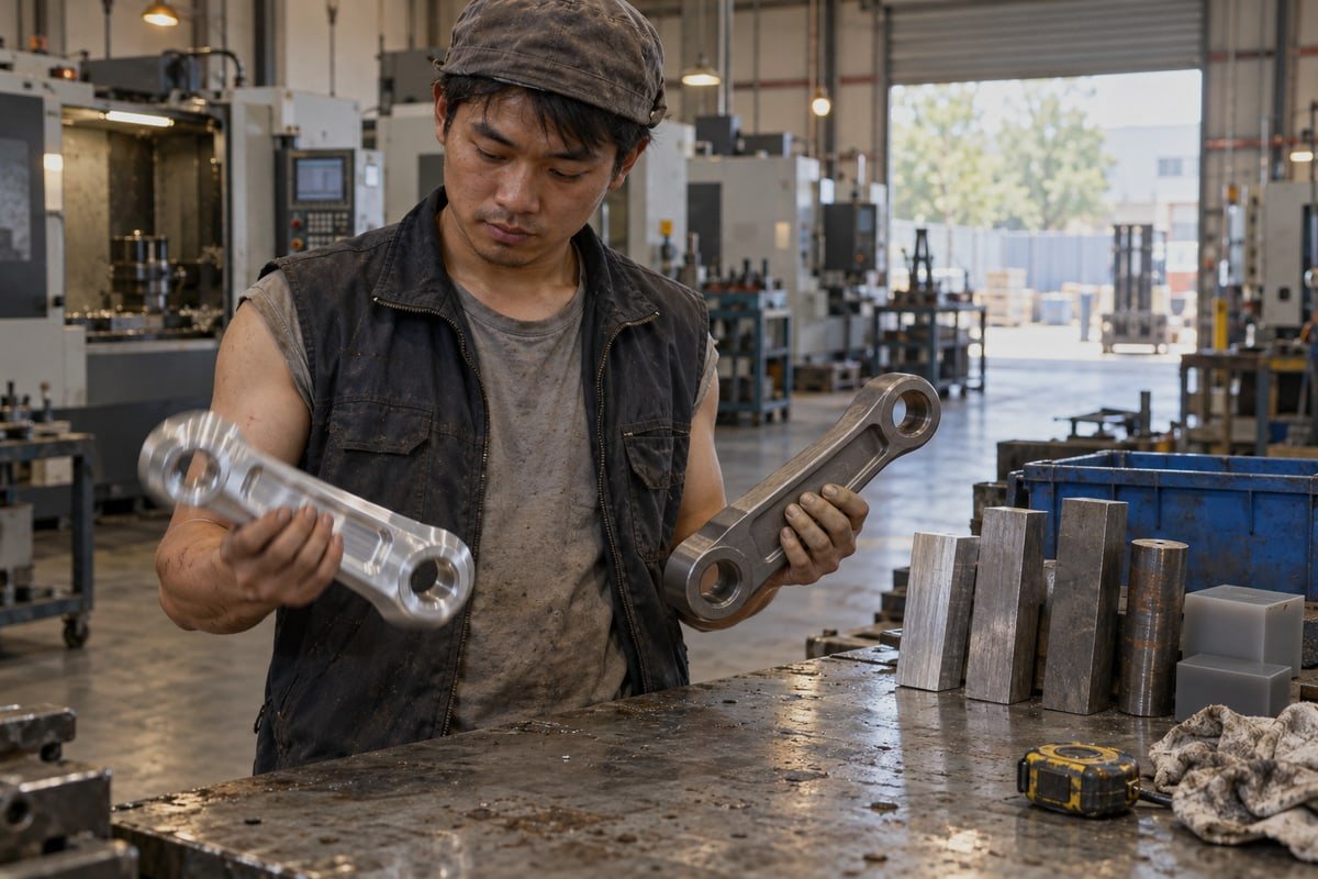
Choose aluminum 6061-T6 or 7075-T6 for arm links, brackets, and end effectors needing low moving mass; alloy or stainless steel for shafts, wear surfaces, and washdown parts; Ti-6Al-4V only where strength-to-weight justifies cost; and engineering plastics like POM or PEEK for insulating, low-load guides.
| Material | Best robotics use | Strength-to-weight ratio | Machining notes | Watch out for |
|---|---|---|---|---|
| Aluminum 6061-T6 2 | Brackets, housings, sensor mounts | Good | Fast, low tool wear, anodizes well | Thread wear in serviced joints |
| Aluminum 7075-T6 | High-load arm links, end effectors | Very good | Slightly harder to cut, higher cost | Lower corrosion resistance than 6061 |
| MIC-6 cast aluminum plate | Large baseplates, long arm segments | Moderate | Stress-relieved, stays flat | Lower strength than wrought alloys |
| Alloy steel 3 | Shafts, gears, heavily loaded joints | Moderate | Slower cutting, may need grinding | Weight, corrosion |
| Stainless 304/316 | Washdown, outdoor, hygienic parts | Moderate | Work-hardens, higher tool wear | Grade mix-ups, longer cycle time |
| Ti-6Al-4V | Joints where weight and strength both matter | Excellent | Slow feeds, heat control critical | High material and machining cost |
| Engineering plastics (POM, nylon, PEEK) | Guides, insulators, low-load bushings | Varies | Easy to cut, needs sharp tools | Moisture, creep, thermal growth |
Aluminum is the default, but not for everything
On our production line, 6061-T6 is the alloy we cut most for robotics. It is light, it machines fast, and it anodizes evenly. When a customer needs more strength in the same envelope, we move to 7075-T6. For large flat baseplates, we suggest MIC-6 plate because it is already stress-relieved and does not warp after pocketing. For arm segments machined from thick wrought stock 4, we sometimes recommend an intermediate stress-relief step before finish cuts.
Aluminum has limits. Threads in soft alloy wear out when a joint is serviced often. We usually recommend thread inserts there. Aluminum is also less stiff than steel, so a thin aluminum link may flex more than the motor controller expects.
Steel, stainless, and titanium have clear roles
Shafts almost always start as CNC turning in alloy steel, then go to grinding if roundness or finish exceeds normal turning capability. Stainless 316 goes into food-grade or washdown robots. We separate 304 and 316 stock physically in our material store because a mix-up is invisible until the part corrodes.
Titanium 5 is a specialist choice. Ti-6Al-4V gives the best strength-to-weight ratio in the table, but it costs several times more to cut. Heat is the enemy. Flood coolant and conservative feeds keep the surface integrity intact. Some shops use cryogenic cooling on titanium to protect fatigue life. For most robot joints, 7075-T6 gets you close enough at a fraction of the price.
What about engineering plastics and 3D printing?
Engineering plastics work well for guides, covers, cable clips, and insulating spacers. POM is stable and cheap. PEEK handles heat and chemicals. Nylon absorbs moisture and grows, so we avoid it in precision fits.
Buyers often raise a fair objection: additive manufacturing 6 wastes less material and allows topology-optimized shapes we cannot mill. That is true for prototypes and complex shells. But printed parts can have anisotropic strength and layer-related surface quality. For a joint that cycles millions of times, we trust isotropic wrought stock. The practical route is hybrid: print the shell, CNC-machine the inserts and bearing interfaces, and pocket the aluminum link with ribs to get most of the weight savings.
How can I ensure consistent quality when scaling from prototypes to mass production?
A German automation buyer told me his last supplier's samples were perfect, then batch thirty arrived with burrs and hole positions off by 0.1 mm.
Ensure consistent quality by locking the drawing revision before batch, approving a first article against a formal inspection report, fixing fixtures and tool paths from the sample, inspecting critical bores and hole patterns in-process, documenting material certificates, and agreeing on packaging and nonconformance handling upfront.

Robotics "mass production" is not what most people picture
Here is the pattern we see in nearly every robotics project: small batches, many variants, and a high degree of customization. A customer rarely orders 5,000 of one bracket. They order 20 of this housing, 40 of that link, and 15 of a modified gripper finger, and they revise two of them next quarter. One industry guide puts the practical CNC range for production-grade robotic components at roughly 10–500 units. Our order book matches that.
This changes how quality has to be managed. You are not stabilizing one big run. You are stabilizing a repeatable process that can be restarted for a dozen part numbers at short notice. That is a different discipline.
The steps we follow from sample to batch
- Freeze the revision. We confirm the drawing and 3D model revision in writing before cutting. Informal model swaps over chat are where batch errors begin.
- Build a proper first article. The sample is machined with the same fixture and program we plan to use for the batch, not a quick one-off setup.
- Inspect and report. Critical bores, hole patterns, flatness, and perpendicularity go on a CMM. The report ships with the sample.
- Lock the process. Once the customer approves, the fixture, tool list, and program are saved against that part number and revision.
- Check in-process. For bearing seats and shaft diameters, the operator measures at set intervals and watches for tool-wear drift.
- Control finishing. We specify whether tolerances apply before or after anodizing, because coating adds thickness.
- Inspect and pack. Outgoing inspection under our ISO 9001:2015 system, then individual protection so parts do not scratch each other in transit.
| What changes | Prototype stage | Repeat batch stage |
|---|---|---|
| Goal | Prove the design works | Prove the process is stable |
| Fixturing | Can be quick and manual | Dedicated, repeatable, stored |
| Inspection | Full dimensional check | Critical features every part, others sampled |
| Documentation | Basic measurements | First article report, material certs, revision log |
| Risk | Design error | Dimensional accuracy drift, burrs, mixed parts |
Why dimensional accuracy drifts
Most batch failures have boring causes. A worn end mill cuts a bore slightly undersize. A fixture clamp loosens over a shift. A second operator loads the part against a different datum face. None of these show up on sample one. They show up on part twenty-five. That is why in-process checks matter more than a perfect first sample.
We also recommend a tolerance-stack analysis before the batch. Small errors on a motor mount, a link, and an end effector can add up to a visible repeatability loss at the tool center point. Knowing which dimensions dominate the stack tells both of us where to focus inspection. We back every shipment with a 30-day warranty, but the real goal is never needing it.
What should I look for in lead times and DFM support when sourcing robotics components?
Twenty years in Dongguan taught us one thing about lead times: the clock does not start at the purchase order. It starts when the drawing is clear.
Look for suppliers who quote lead times by part complexity, offer rapid prototyping in roughly 5 days for simple parts, flag cost-driving features in a written DFM review, suggest standard radii and thread inserts, and confirm whether anodizing or heat treatment changes final dimensions before cutting.

What really sets the lead time
Buyers often ask for a single number. The honest answer is a range that depends on the part. Our fastest rapid prototyping jobs ship in as short as 5 days when the design is a simple aluminum bracket with a clear drawing. A five-axis titanium housing with anodizing and a full CMM report takes longer. Neither number is wrong. They are just different parts.
| Factor | Shortens lead time | Lengthens lead time |
|---|---|---|
| Drawing package | 2D with datums, GD&T, finish notes | 3D model only, missing thread specs |
| Material | Stock 6061-T6, 304, POM on hand | Special titanium grade, tool steel on order |
| Process | Three-axis, few setups | Five-axis plus wire EDM plus grinding |
| Finishing | None or in-house deburr | Outsourced plating, masking, color matching |
| Inspection | Standard outgoing check | Full CMM report, material certificates |
| Order structure | Related parts grouped together | Many single-piece orders over weeks |
That last row matters for robotics. Because projects are small-batch and multi-variant, we ask customers to group related components in one order. A link, its motor mount, and its sensor bracket can share stock, fixtures, and programming time. That lowers both lead time and price per piece.
What good DFM feedback looks like
DFM is not a sales gesture. It is a written review that comes back with the quote. When our engineers open a robotics drawing, they look for specific things:
- Setups. Can the bearing bore and mounting face be cut in one clamping? If not, can a small design change make that possible?
- Internal corners. Milling cutters are round. A sharp internal corner forces wire EDM or a tiny cutter. A standard radius avoids both.
- Thin walls and deep pockets. Walls that are too thin vibrate and distort. Deep narrow pockets need long tools that deflect. We suggest ribs or revised depths.
- Threads in aluminum. For serviced joints, we propose inserts. For blind holes, we check that drill depth is realistic.
- Weight reduction. Pockets are fine, but we check that material stays around bearing seats, dowel holes, and the main load path.
- Finishing. We ask whether the ±0.02 mm bore is specified before or after anodizing, and which faces need masking.
- Tolerances. We point out any feature where a ±0.05 mm general tolerance would work instead of a tighter call-out.
Questions to ask before you commit
A supplier with engineering understanding will answer these quickly:
- Which three features on this drawing drive the most cost?
- What secondary operations are needed, and are they in-house?
- Will you provide a first-article inspection report and material certificate?
- If I revise the part, how do you prevent old-revision stock from shipping?
- Can you hold the same lead time on the reorder next quarter?
The sign of a good partner is not the shortest quoted lead time. It is a lead time that matches what actually ships, batch after batch.
Conclusion
A robot is only as repeatable as its weakest bore. Define function first, tolerance only what matters, and choose a shop that proves precision with reports, not promises.
Footnotes
1. Wikipedia entry explaining the technical principles and advantages of multi-axis CNC machining centers. ↩︎
2. Official site for ASM International, the leading authority on materials science and metal alloy properties. ↩︎
3. Comprehensive reference for the composition and industrial applications of various alloy steel grades. ↩︎
4. Technical definition and engineering context for wrought alloys versus cast materials. ↩︎
5. Scientific overview of titanium properties from the Royal Society of Chemistry. ↩︎
6. NIST resource page covering standards and research for additive manufacturing technologies. ↩︎

 English
 Italiano
 Français
 日本語
 Deutsch (Sie)
 Español
 Русский
 العربية
 Български
 Čeština
 Dansk
 Suomi
 עִבְרִית
 हिन्दी
 Nederlands
 Português
 Română
 Slovenčina
 Svenska
 ไทย
 Tiếng Việt
 Türkçe
 Slovenščina