

A customer’s valve seat was a few microns out. It leaked. The test run was wasted. That failure showed our shop why CNC machining for laboratory equipment manufacturing matters.
CNC machining improves laboratory equipment manufacturing by turning CAD models into parts with tight tolerances, repeatable dimensions, and controlled surfaces. It handles special materials like PEEK, titanium, and 316 stainless steel, supports small batches without tooling costs, and lets engineers iterate designs quickly.
That is the short answer. The longer answer is more useful. Lab instruments live or die on alignment, sealing, and repeatable positioning. Below, I walk through how we approach precision, material choice, batch consistency, and prototyping for custom laboratory components in our Dongguan factory.
How can CNC machining help me achieve the precision my lab equipment components require?
Every quote for an optical mount forces a trade-off. Tighter tolerances cost more machine time. Looser ones risk misalignment. Our engineers settle it by asking which features affect the measurement.
CNC machining achieves lab-grade precision through programmed tool paths, calibrated multi-axis machines, controlled feeds and speeds, and in-process inspection. Realistic process tolerances of 0.01–0.005 mm are possible on critical features, but each must be verified by measurement, not assumed from machine specifications.
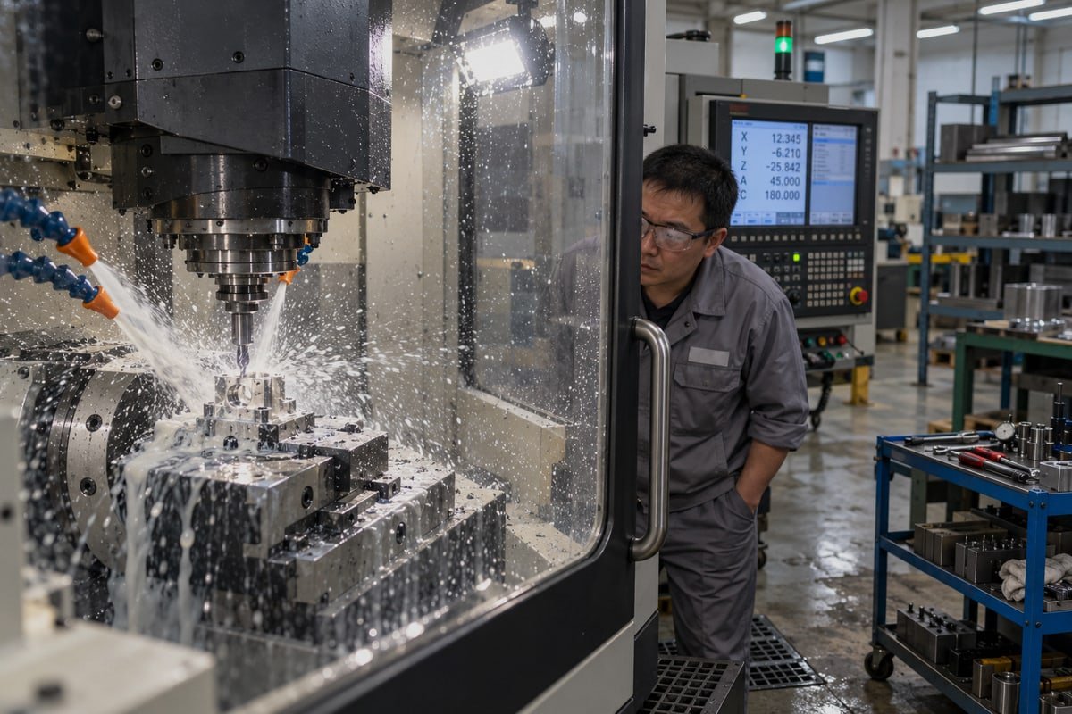
Precision is the first reason buyers search for CNC machining in laboratory equipment manufacturing. It is also the most misunderstood. Many ranking pages promise "micron-level precision" as if it comes free with the machine. In our experience, it does not. Tolerance is an engineered outcome. I want to break it into three separate ideas.
Machine resolution, process tolerance, and verified tolerance
These three numbers are not the same. A buyer who confuses them will be disappointed. Here is how we explain the difference to customers.
| Term | What it means | Who controls it |
|---|---|---|
| Machine resolution | The smallest step the axis can command, often 0.001 mm | The machine builder |
| Process tolerance | What the whole setup can hold on a real part: fixture, tool, material, temperature | The machinist and programmer |
| Verified tolerance | What the inspection report actually proves, with measurement uncertainty included | The QC team and their calibrated gauges |
A machine with 0.001 mm resolution does not produce 0.001 mm parts. Tool deflection, thermal growth of the spindle, residual stress in the billet, and workholding all eat into that number. On our 3-axis, 4-axis, and 5-axis mills, we quote 0.01 mm as routine and 0.005 mm on selected features. We only quote the tighter number after we have looked at the geometry and material.
Accuracy versus repeatability
Accuracy means the bore is the size the drawing asked for. Repeatability means bore number fifty matches bore number one. For analytical instrument components, repeatability often matters more. A repeatable process reveals systematic error. If every part is 0.004 mm large, we adjust one tool offset and fix all of them. A random process cannot be corrected that way.
Where tight tolerances actually matter
Here is where I push back on over-tolerancing. A lens holder needs flat datums and accurate hole positions. The outside of its housing does not. A pump body needs its bore and seal face controlled. The cosmetic chamfers do not. Functional tolerancing keeps dimensional accuracy where it counts and keeps your invoice reasonable.
For optical mounts 1 in particular, we also plan stress relief into the sequence. Rough machining, a stabilizing step, then finish machining. Skipping that step is how a part measures perfectly on Friday and drifts by Monday.
What materials should I choose for CNC machined laboratory equipment parts?
A product manager in Germany sent us a drawing marked only "stainless steel." We asked whether the part would see chloride cleaning agents. That question changed the grade to 316.
Choose materials by lab exposure: 6061 or 7075 aluminum for housings and mounts, 316 stainless steel for fluid paths and chemical contact, titanium for strength with corrosion resistance, and PEEK, PPSU, or POM for insulation, sterilizability, and low friction. Always demand material certificates.
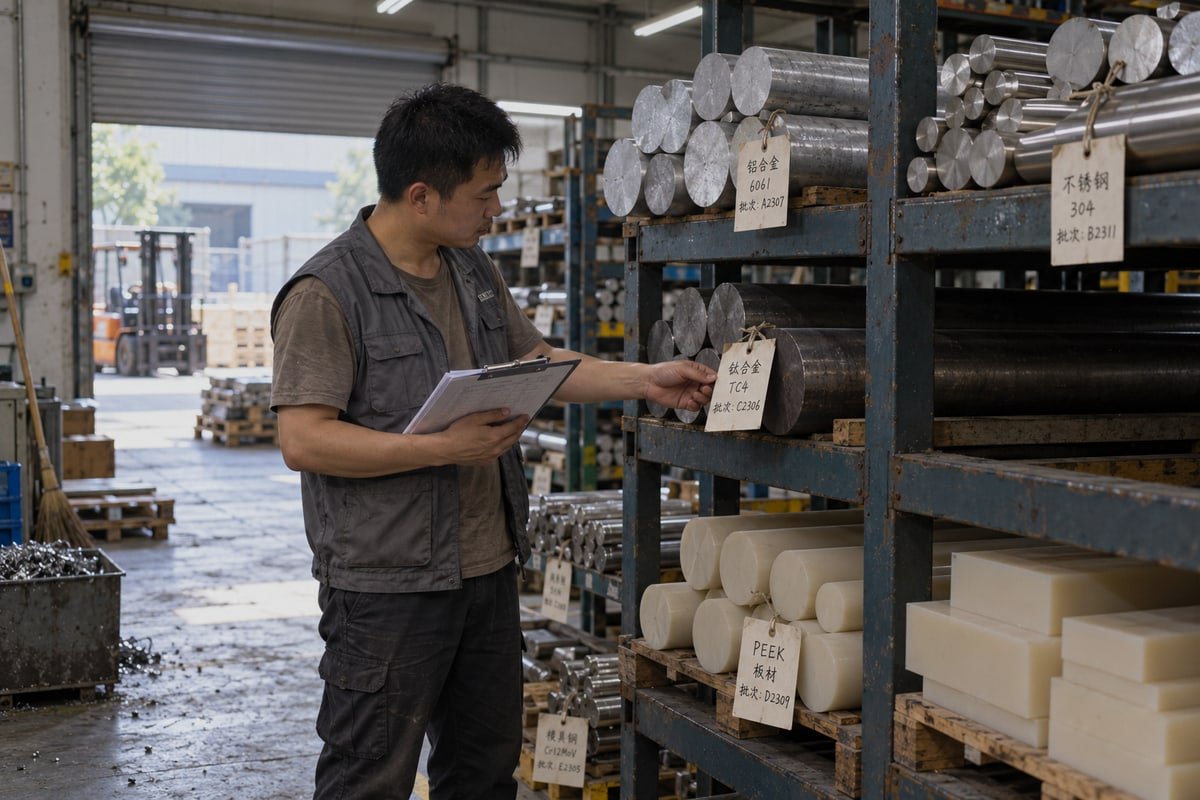
Material selection is where small-batch lab projects differ most from consumer work. A consumer bracket is usually ordinary aluminum in large volume. A lab part is often a special material in a quantity of five. That combination defines much of what we do for laboratory customers. So I want to be direct about what each material does and what it costs you in machining.
Matching material to the laboratory environment
| Lab requirement | Suggested material | Machining note |
|---|---|---|
| Lightweight housings, optical mounts, frames | 6061 or 7075 aluminum | Easy to machine; anodize for wear and corrosion |
| Fluid contact, reagents, autoclave cycles | 316 stainless steel | Slower cutting; passivate after machining |
| Strength plus corrosion resistance, low mass | Titanium | Higher tool wear; expect longer cycle times |
| Electrical insulation, sterilizable, biocompatible | PEEK, PPSU | Heat-sensitive; needs controlled feeds and cooling |
| Low friction sliding parts, sample trays | POM (Delrin) | Stable and cheap; watch for chip recutting |
| Chemical resistance, low cost fixtures | HDPE, PC, nylon | Soft; hold with care to avoid distortion |
Special materials in small batches
This is the part of the business I care about most. A batch of twenty PEEK manifolds or ten titanium sensor brackets 2 is not economical for most large shops. For us it is normal work. Medical-grade materials and biocompatible plastics such as PEEK and PPSU behave differently from metals under the cutter. They hold heat. They move. A pocket that measures correctly while warm can shrink out of tolerance after cooling. We slow the feed, use sharp tooling, and let the part normalize before final inspection. Some shops go further and use cryogenic cooling on heat-sensitive polymers to stop warping. The principle is the same: control heat, or the plastic controls you.
Documentation and traceability of material
Material fraud is a real fear for overseas buyers. Mixing 304 and 316, or swapping 6061 for an unknown aluminum, ruins corrosion resistance and strength. We attach mill certificates 3 to the shipment and keep the heat number in the batch record. Customers running ISO 13485 compliance 4 systems for medical and lab devices need this trail for their own audits. We are ISO 9001:2015 certified ourselves, and our paperwork is built to plug into theirs.
Surface finish as part of material choice
Material and finish go together. Stainless fluid parts get passivation. Aluminum optical housings get black anodizing to cut stray reflections. Surface finish quality on seal faces and O-ring grooves is specified by function, not polished everywhere. Polishing a non-critical face only adds hours to your quote.
How does CNC machining ensure consistent quality across batches of my lab equipment components?
During a 200-piece run of sample holders, our in-process probe flagged a 0.008 mm drift on the fifth part. We stopped, swapped the worn end mill, and saved the batch.
CNC machining ensures batch consistency because the same CAM program, fixtures, and tool offsets reproduce identical tool paths on every part. Combine this with first-article inspection, in-process probing, CMM sampling, and revision-controlled files, and dimensional drift between batches becomes detectable and correctable.
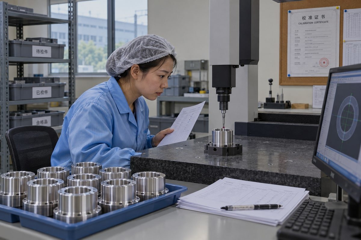
The most common complaint I hear from new customers is simple. The sample was perfect. The batch was not. Holes shifted, threads tore, surfaces scratched. CNC machining can prevent this, but only when it is treated as a process, not a single event. Here is how we run a laboratory batch.
A batch-control process in seven steps
- Freeze the revision. The CAD, CAM, and drawing revision are locked and named. Nothing changes without a new revision number.
- Build the fixture. For multi-side parts we design a dedicated fixture so every part sits in the same datum. Soft jaws and vacuum plates are documented with photos.
- First-article inspection. The first part is measured against every drawing dimension. We send the FAI report before cutting the rest.
- In-process probing. The machine checks critical bores and datums during the run. Tool wear shows up as a trend before it becomes a reject.
- Sampling by CMM. A set frequency of parts goes to the coordinate-measuring machine. Calipers and micrometers cover simple features; the CMM covers position and form.
- Outgoing inspection. Final dimensional check, visual check for burrs and scratches, thread gauge on every tapped hole.
- Batch record. Material cert, machine, program revision, operator, and inspection data are stored against the lot number.
Which inspection tool verifies which feature?
| Feature type | Typical tool | Why |
|---|---|---|
| Bore diameter | Bore gauge, air gauge | Fast, repeatable, operator independent |
| Hole position pattern | CMM | Measures true position relative to datums |
| Flatness of optical datum | CMM or surface plate with indicator | Form error, not just size |
| Thread quality | Go/no-go thread gauges | Catches torn or shallow threads |
| Surface finish | Profilometer | Objective Ra value for seal faces |
Automation and lights-out running
For repeat lab components, we move stable jobs onto pallet systems with automatic tool changers. The machine runs through the night. This is not just about throughput. A machine that loads itself does it the same way every time. Human loading variation disappears. Probing between pallets catches drift without anyone standing there.
Consistency also means standing behind the parts. Our 30-day warranty exists because a batch problem should be our cost, not yours. The CAD/CAM integration behind all of this is what makes a rework quick: we pull the revision, adjust, and recut without reverse-engineering anything.
Can CNC machining support rapid prototyping for my laboratory equipment development projects?
Twenty years of machining left us one hard lesson: a 3D-printed model can hide problems that only appear in real aluminum. Prototypes need production materials.
Yes. CNC machining supports rapid prototyping by cutting functional parts directly from CAD files in production-grade metals and plastics, with no molds required. Lead times can be as short as 5 days, so engineers can test fit, sealing, and alignment, then revise and re-machine within days.
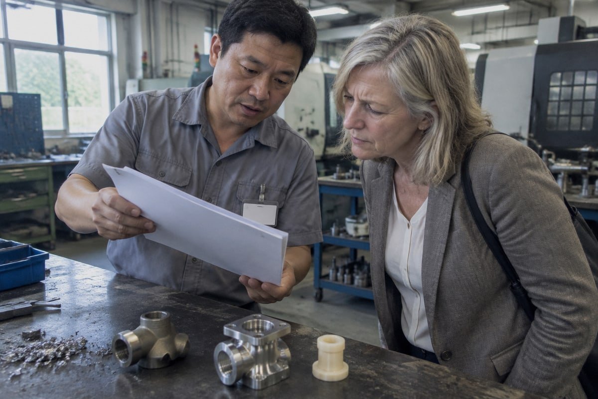
Prototyping is where CNC machining earns its place in laboratory equipment manufacturing. Lab instruments change during research. A fluid path moves. A sensor gets bigger. A mount needs a second degree of adjustment. You need a process that follows the design without a tooling penalty. Let me start with the comparison buyers ask for most.
CNC versus injection molding versus 3D printing for lab prototypes
| Factor | CNC machining | Injection molding | Additive manufacturing |
|---|---|---|---|
| Time to first part | Days | Weeks, after mold build | Hours to days |
| Tooling cost | None | High | None |
| Material properties | Full bulk properties of real alloy or polymer | Production material, but only after mold exists | Often lower strength, anisotropic |
| Dimensional accuracy | High, 0.01 mm achievable | High once tuned | Moderate |
| Surface finish on seals and bores | Good, controllable | Good | Usually needs post-machining |
| Internal lattices and curved channels | Limited | Limited | Excellent |
| Best volume range | 1 to several hundred | Thousands and up | 1 to tens |
| Design change cost | Reprogram and recut | Modify or rebuild mold | Reprint |
The iteration loop we run with customers
- The engineer sends a STEP file and 2D drawing.
- Our team returns a DFM review within a day. We flag thin walls, deep pockets, and tolerances that will cost more than they help.
- CAM is programmed and the part is cut, often on a 5-axis machine to avoid multiple setups.
- The part ships with an inspection report.
- The customer assembles it into the instrument and tests fit, sealing, or optical alignment.
- The revision comes back. We cut again.
Because changes happen in software, not in steel tooling, the second round is often faster than the first.
When CNC is the wrong choice, and how we handle it
I will not pretend CNC wins every time. If your part has an enclosed serpentine channel, additive is better. If you need ten thousand identical plastic trays, molding is cheaper per piece once the mold is paid off. If a tiny turned pin is needed in volume, Swiss screw machining may beat conventional turning. And if a surface demands optical-grade flatness, grinding or lapping finishes what milling starts. We tell customers this upfront. It costs us a few quotes, but it keeps them coming back for the parts that CNC does best.
Pushing the edge of prototyping
Two newer uses are worth knowing. Micro-milling can cut microfluidic channels 5 directly into PMMA or COC, offering a fast alternative to lithography for small runs. And engineered toolpath textures can give a surface hydrophobic or anti-fouling behavior without coatings. Both are still prototyping tools in our view, but both fit the small-batch, special-material nature of lab work.
Wire EDM also matters here. Sharp internal corners and hardened steel features that a cutter cannot reach become routine. For a one-off instrument bracket, that flexibility is the difference between a working prototype and a redesign.
Conclusion
Inconsistent parts quietly undermine lab results. Costly recalls follow. CNC machining, paired with functional tolerancing, verified materials, and documented inspection, gives laboratory equipment makers parts they can trust.
Footnotes
1. Authoritative source for optics and photonics, relevant to the precision engineering of optical mounts for laboratory equipment. ↩︎
2. Authoritative overview of titanium properties, a key material for specialized laboratory sensor components. ↩︎
3. ASTM International provides the standards for material testing and the documentation required for mill certificates. ↩︎
4. Official ISO standard for quality management systems specifically for medical devices and related laboratory equipment. ↩︎
5. Scientific resource for microfluidics, explaining the application of micro-milled channels in laboratory research. ↩︎

 English
 Italiano
 Français
 日本語
 Deutsch (Sie)
 Español
 Русский
 العربية
 Български
 Čeština
 Dansk
 Suomi
 עִבְרִית
 हिन्दी
 Nederlands
 Português
 Română
 Slovenčina
 Svenska
 ไทย
 Tiếng Việt
 Türkçe
 Slovenščina