
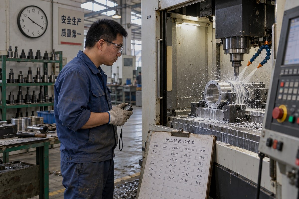
Reducing CNC machining cycle time starts with the real cycle, not the programmed one. A buyer’s housing job once ran twice its CAM estimate on our floor. His deadline slipped.
To reduce CNC machining cycle time, measure the full cycle first, then cut non-cutting time: air moves, long retracts, tool changes, and setups. Next, optimize roughing strategy, feeds, and tooling. Finally, reduce setups with better fixtures, and verify quality so faster parts stay conforming.
That order matters. Most shops jump straight to higher feeds. We do the opposite. We hunt for wasted motion and waiting first, because those gains are free and safe. Below, I walk through the four questions our engineers ask on every job.
How can I identify the biggest bottlenecks slowing down my CNC machining cycle time?
The lesson our engineers learned early: a stopwatch beats a CAM estimate. We time loading, probing, tool changes, and cutting separately before touching a single feed rate.
Identify bottlenecks by timing each stage of the real cycle separately: loading, probing, cutting, rapid moves, tool changes, inspection, and waiting. Compare actual machine time with programmed time. The largest gap, often non-cutting time, is your first target.
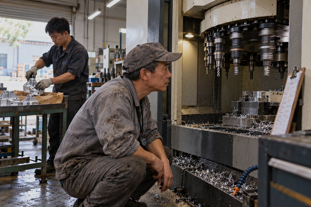
Most cycle-time problems are invisible if you only look at the toolpath. The CAM screen shows cutting. It does not show the operator walking to find a gauge. It does not show the turret pausing on an M-code timer. So the first job is to define what you are measuring and then break it into pieces.
Define the measurement boundary first
Cycle time can mean one part, one pallet, one batch, or one full machine cycle. Pick one boundary and stick to it. For a single cylindrical housing with a bolted bracket, like the ones we run for optical equipment customers, we measure spindle-start to spindle-start on the next part. That includes unloading, deburring, and loading. If you measure only cutting, you will optimize the wrong thing.
The formula we write on the setup sheet is simple:
Total cycle time = cutting time + tool-change time + rapid-motion time + probing and inspection time + loading and unloading time + waiting or dwell time
Break the cycle into components
| Component | What hides inside it | How we measure it |
|---|---|---|
| Cutting time | Feeds, speeds, depth of cut, number of passes | Machine data or CAM backplot, then verified at the control |
| Rapid and air moves | Returns to machine zero, high clearance planes, air cutting | Backplot review, stopwatch on dry run |
| Tool changes | Chip-to-chip time, carousel order, spindle acceleration | Count changes × measured chip-to-chip time |
| Probing and dwell | Redundant probe cycles, dwell commands, M-code timers | Read program line by line |
| Loading and unloading | Fixture clamping, part cleaning, chip removal | Stopwatch, operator observation |
| Waiting | Searching for tools, gauges, drawings, approvals | Shop-floor observation over several parts |
Compare programmed time with actual time
Once you have the real numbers, line them up against the CAM estimate. The difference tells a story. A big gap in rapid moves usually means the machine never reaches its programmed rapid rate because of acceleration limits. A big gap in tool changes points at the automatic tool changer sequence or a poor tool order. A big gap in waiting points at the kit, not the machine.
On the housing job I mentioned, the cutting time matched the estimate almost exactly. The doubling came from fourteen tool changes, a retract to machine zero after every operation, and the operator measuring every bore by hand. None of that was a cutting problem. All of it was fixable without raising a single spindle speed.
What design changes can I make to my parts to speed up machining without sacrificing quality?
A German customer asked why his enclosure quoted with a far longer cycle than a similar part. Our DFM review found two causes: tiny internal corners and a deep, narrow pocket.
Speed up machining by designing for standard tools: use internal radii larger than common end mills, limit pocket depth to a few times tool diameter, apply tight tolerances only where function demands, keep walls thick enough to resist deflection, and consolidate features so the part needs fewer setups.
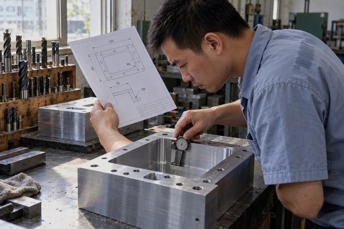
Cycle time is often decided before the drawing reaches us. A round cutter cannot produce a sharp internal corner. A thin wall cannot take a heavy cut without ringing. These are physics, not supplier excuses. The good news is that most of these features can be changed without touching function. That is why we give DFM feedback on every drawing uploaded to us, whether the order is one prototype or a batch for mass production.
Corners, pockets, and walls
Small internal radii force us to use small tools. Small tools need slow feeds and many passes. If a radius is smaller than any standard end mill 1, the feature may need wire EDM, which adds a whole operation. Deep, narrow pockets have the same effect. The tool has to stick out further, so we lower the feed to avoid deflection and chatter. Thin walls force light cuts and extra finishing passes.
| Feature on the drawing | Why it slows machining | Better choice | Quality risk if left alone |
|---|---|---|---|
| Internal corner radius smaller than 1 mm | Tiny tool, slow feed, many passes, or EDM | Radius matched to a standard end mill, or add a corner relief | Chatter marks, broken tools, extra rework |
| Pocket depth far beyond tool diameter | Long tool overhang, reduced feed, vibration | Shallower pocket or a stepped floor | Deflection, taper on walls |
| Thin walls | Light cuts, multiple finish passes, distortion | Thicker wall or added ribs | Out-of-flatness, surface waviness |
| Tight tolerance on every dimension | Extra finishing, probing, and inspection | Tight tolerance only on critical mating features | Longer inspection, higher scrap |
| Non-standard hole sizes | Custom drills, extra reaming, more tool changes | Standard drill and tap sizes | Tool availability delays |
Tolerances and features
Our milling machines hold 0.01 mm, and down to 0.005 mm on selected features. But holding that on every dimension is expensive. Each tight dimension means a finishing pass, often a probing cycle, and a line on the inspection report. Put the tight tolerance on the bore that seats the bearing and the face that seals. Leave the outside profile at a general tolerance. The part works the same. The cycle gets shorter.
Standardize holes and materials
On the mold bases we machine, standard alignment pins and standard hole sizes let us run one drill set across the whole plate. That cuts tool changes and tool-change waiting. The same logic applies to materials. Common grades such as 6061 aluminum, 304 or 316 stainless, brass, and POM are stocked and have proven cutting data. Exotic grades need trials, and trials eat time.
One warning. DFM changes need engineering sign-off on your side. We will never simplify a feature that affects fit, sealing, fatigue life, or a regulatory requirement. We flag the opportunity. You decide.
Which CNC programming and tooling strategies help me cut cycle time on complex parts?
Every time we program a complex 5-axis part, we weigh the same trade-off: adaptive roughing cuts spindle time, but sloppy linking moves add air cutting that gives it back.
Cut cycle time on complex parts with adaptive or trochoidal roughing, rest machining with larger tools first, optimized peck drilling, fewer tool changes through consolidated tool lists, minimum safe retract planes, smooth linking moves, and feeds matched to tool coating, engagement, and machine rigidity.
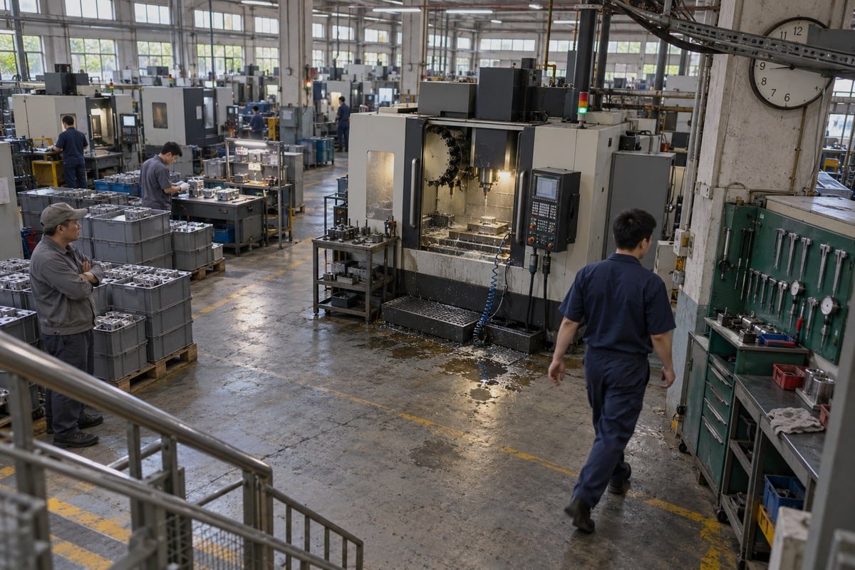
Programming is where most of the cutting-time gains live, and also where most of the hidden non-cutting time lives. We treat the two together. A great roughing strategy with bad linking is not a great program.
Pick the roughing strategy by real spindle-to-spindle time
Roughing removes most of the material, so it is the first cutting target. The options below are not ranked. Each one wins in a different situation.
| Strategy | Best suited for | Main benefit | What to watch |
|---|---|---|---|
| High-efficiency machining / adaptive clearing | Large stock removal, variable engagement | Constant radial engagement, higher axial depth 2, steady load, higher MRR | Many short blocks; needs good control look-ahead |
| Trochoidal milling | Slots, pockets, tough materials like titanium and Inconel | Avoids full-width engagement, less heat and shock | Can produce long paths if poorly configured |
| High-feed milling | Shallow axial cuts on faces and open areas | Very high feed rates with thin chips | Needs a rigid setup and suitable inserts |
| Conventional full slotting | Short, simple, rigid cuts | Simple program, short path | Heavy tool load, lower feed, more wear |
The honest comparison is actual time, tool life, surface finish 3, and the condition of the stock left for finishing. Not the name of the strategy. We have seen adaptive paths lose to a plain slot cut on a short, stiff feature, simply because the adaptive path spent its time in linking moves.
Shrink non-cutting motion inside the program
This is the point I care about most, and it is the first thing we check on every program: minimize air cutting and non-cutting time. The steps we follow are:
- Run a backplot and look for rapid moves that climb to a high clearance plane after every pass.
- Set the retract height to the minimum safe value after verifying fixture, clamp, and holder geometry in simulation.
- Remove returns to machine zero between operations.
- Replace stop-and-retract transitions with smooth arcs where the control supports high-speed machining settings.
- Delete redundant dwells and check M-code completion timers.
- On lathes, synchronize X and Z rapids and shorten turret retract positions.
- Confirm the machine actually reaches the programmed rapid rate. Short moves often never do.
Each step saves seconds. Seconds repeat on every part. On a batch of thousands, that is hours.
Cut tool changes and repeated operations
Every tool change costs chip-to-chip time, plus spindle acceleration. So we review the tool list. Can one tool chamfer and spot? Are two near-identical end mills loaded for a minor difference? Then we use rest machining: a large tool clears bulk material, and a small tool only visits the corners it cannot reach. Tool order in the automatic tool changer is set to avoid long carousel travel.
Drilling gets its own review. We reduce peck depth and frequency to what chip evacuation needs, use partial chip-break retracts instead of full withdrawal, and specify through-coolant carbide drills for deep holes. Where the drill geometry and hole tolerance allow, we drop the spotting operation. But we validate hole position on the first article before we remove it from the program.
Tooling and feed rate optimization
Material removal rate is the quick check:
MRR = axial depth of cut × radial width of cut × feed rate
Spindle speed does not appear in that formula. Raising axial depth or feed usually buys more time than raising RPM alone. For tooling, we use the largest practical diameter for rigidity, standard tools wherever possible, and coatings matched to the material. AlTiN coatings let us push steel and stainless harder. PCD tooling holds up on abrasive aluminum alloys and some plastics. For heat-sensitive superalloys, MQL or cryogenic cooling can support higher cutting speeds, but only on a machine and fixture that are rigid enough to use them. We start from the toolmaker's catalog values, then run controlled trials and adjust by chip load rather than guessing.
How do I balance faster cycle times with maintaining tight tolerances and consistent quality?
Our inspection team once flagged a bore drifting toward its 0.01 mm limit mid-batch. The machine was fine. A faster feed had shortened tool life, and the edge wore early.
Balance speed and quality by judging changes on cost per good part, not programmed time. Keep aggressive parameters for roughing, leave consistent stock for finishing, use in-process probing to catch drift, monitor tool wear, and maintain machine condition so tight tolerances repeat across the whole batch.
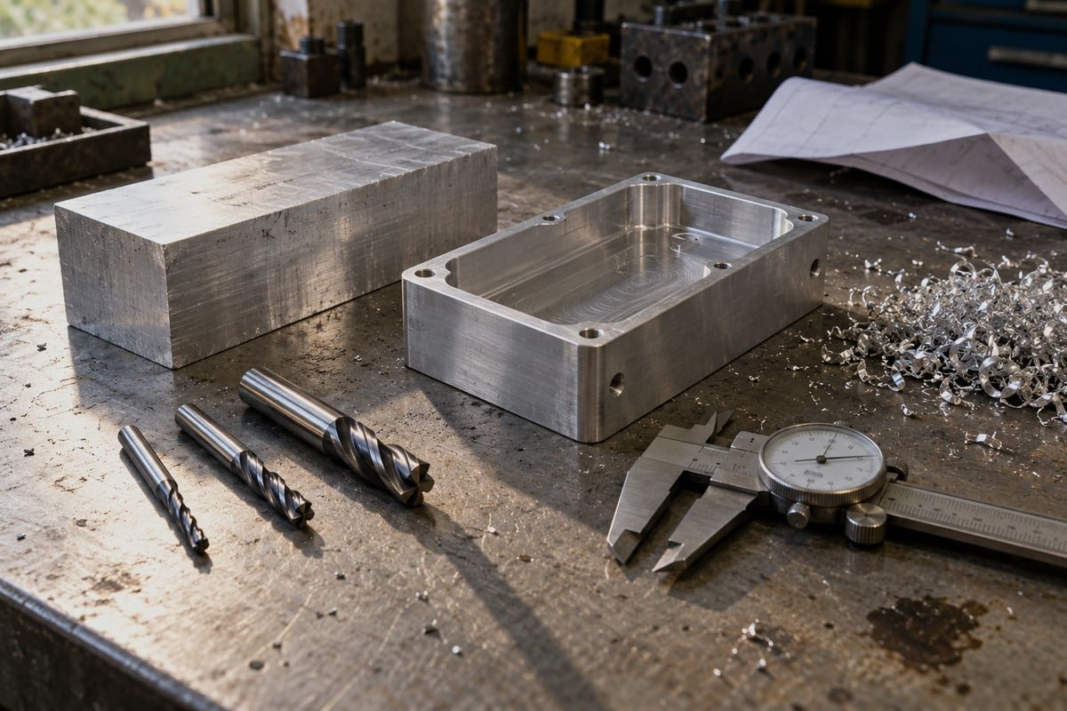
The fastest cut is not the fastest accepted part. That is the whole argument of this section. A buyer who orders medical device components 4 or optical housings from us does not care that we saved forty seconds if one part in fifty fails assembly. So every speed change we make has to pass a quality test before it stays in the program.
Separate roughing from finishing
We push roughing hard and keep finishing stable. Roughing is where high-efficiency machining earns its keep. Finishing is where we hold our tolerances, so finishing feeds and spindle speed stay at the values that produce a predictable surface and a predictable size. The key link between the two is the stock left after roughing. An aggressive roughing pass that leaves uneven stock makes the finish tool work harder in some places than others. That shows up as dimensional variation. We check the roughed stock on the first article before we trust a new roughing strategy.
Probing: seconds spent, minutes saved
A common objection from buyers is that probing adds time to the cycle. It does. A probe cycle takes seconds. But it replaces manual indicating during setup, it catches a misloaded part before the tool hits it, and it updates offsets when a tool wears. On that drifting bore, a mid-batch probe check would have caught the trend before any part went out of tolerance. We now treat probing as part of the quality system 5, not as a cycle-time cost. On repeat jobs it also feeds the first article inspection report and dimensional reports our customers need for their own acceptance process.
Setups, workholding fixtures, and automation
Each setup adds loading, alignment, probing, and error risk. Reducing setups is a quality move as much as a speed move. Multi-axis machining lets us reach several faces in one clamping. Tombstones and multi-part fixtures raise output per cycle. Zero-point locating and quick-change vises move setup time reduction off the machine, so the next job is staged while the spindle is still cutting. We also separate internal setup, which needs the machine stopped, from external setup, which does not. Tool presetting, program verification, and a complete pre-job kit all happen outside.
Two more objections deserve a straight answer. First, five-axis and mill-turn machines 6 cost more and need more skilled programming. We only recommend them when the total cost per finished part drops, not because the machine is capable. Second, multi-part fixtures amplify scrap: one broken tool can ruin eight parts. So we add automation, bar feeders, or pallet changers only after the process is proven stable with tool-life monitoring in place. Automating an unstable process multiplies downtime.
Track cost per good part
Programmed cycle time is a weak metric on its own. We keep a short scorecard on every optimization project and run it inside our ISO 9001:2015 system.
| Metric | Why it matters | Direction we want after a change |
|---|---|---|
| Actual cycle time | The real spindle-to-spindle number | Down |
| Non-cutting time percentage | Shows whether the waste is really gone | Down |
| Tool life per edge | Faster feeds can hide tool-change cost | Stable or up |
| First-pass yield | Catches quality loss from speed gains | Stable or up |
| Setup time | Verifies fixture and kit improvements | Down |
| Scrap and rework rate | Reveals hidden cost of aggressive cuts | Down |
| Cost per good part | The final judge of any change | Down |
The formula is plain:
Cost per good part = total production cost ÷ number of acceptable parts
If a change lowers programmed time but raises scrap or inspection effort, the formula tells the truth. Along with regular spindle, axis, coolant, and runout maintenance, this scorecard is what lets us promise lead times as short as 5 days and still ship parts that match the drawing in batch, not only in the first sample.
Conclusion
Cutting CNC machining cycle time means finding waste. Measure the real cycle, remove air cutting and waiting, and optimize cutting and setups. Send us a drawing; we'll find hidden time.
Footnotes
1. NIST manufacturing portal providing resources on industrial standards and advanced machining technology. ↩︎
2. Technical resource explaining engineering principles of material removal rate and axial depth in machining. ↩︎
3. Technical definition and overview of surface finish requirements in industrial manufacturing processes. ↩︎
4. FDA regulatory information for medical device components, relevant to the high-precision quality requirements mentioned. ↩︎
5. Official ISO page for the quality management standard used for process optimization and quality control. ↩︎
6. Wikipedia overview of multi-axis machining technology, including 5-axis and mill-turn machine configurations. ↩︎

 English
 Italiano
 Français
 日本語
 Deutsch (Sie)
 Español
 Русский
 العربية
 Български
 Čeština
 Dansk
 Suomi
 עִבְרִית
 हिन्दी
 Nederlands
 Português
 Română
 Slovenčina
 Svenska
 ไทย
 Tiếng Việt
 Türkçe
 Slovenščina