
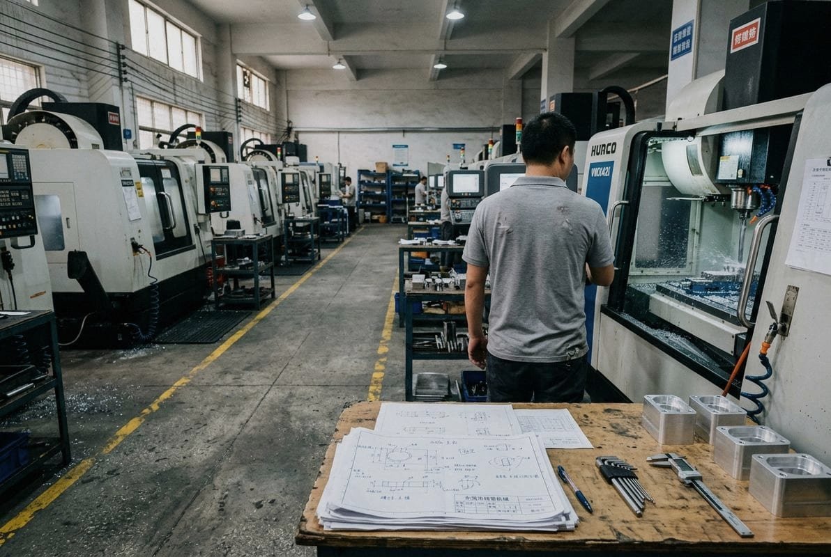
Every week, our engineering team in Dongguan reviews dozens of part drawings from buyers worldwide — and the same question keeps surfacing: will CNC machining 1 work for this part, or will it hit a wall?
CNC machining delivers high precision, excellent repeatability, and broad material versatility for complex parts, but it carries a high initial investment, generates material waste, and struggles with very thin, very soft, or highly irregular geometries — making it essential to understand both sides before committing.
Below, I break down the core advantages and real-world limitations we encounter daily on our shop floor CAD/CAM software 2. Whether you are sourcing prototypes or planning a production run, this guide will help you decide when CNC is your best option — and when a different process might serve you better.
How does CNC machining ensure the high precision I need for my complex parts?
A U.S. aerospace client once sent us a turbine impeller drawing with tolerances at ±0.005 mm on critical blade surfaces — the kind of spec that keeps machinists up at night PEEK polymer 3.
CNC machining ensures high precision through digital coordinate control, rigid multi-axis setups, and programmed toolpaths that achieve tolerances as tight as ±0.005 mm, virtually eliminating human error and delivering identical results across every single part in a batch.
Why Digital Control Matters
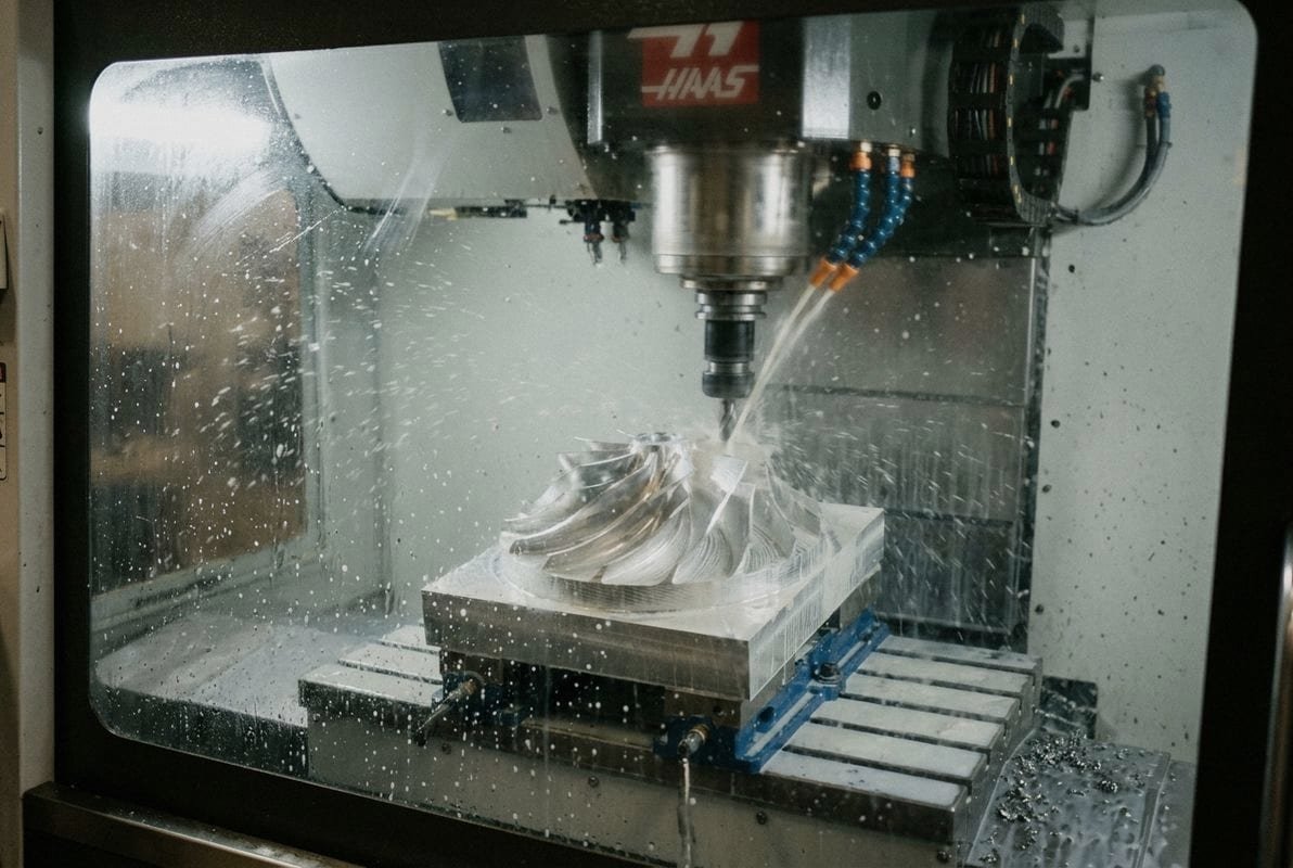
Traditional machining relies on a skilled operator's hands, eyes, and experience. CNC replaces that variability with exact digital instructions. Our 3-axis, 4-axis, and 5-axis machines read G-code 4 generated by CAD/CAM software and follow every coordinate to the micron. The spindle speed, feed rate, depth of cut, and tool angle are all calculated before the first chip flies. This means the machine does not guess. It executes.
Multi-Axis Capability for Complex Geometries
Simple 3-axis mills handle flat surfaces and basic pockets well. But parts like the radial impeller wheels and multi-level cylindrical components we produce demand simultaneous 5-axis movement 5. The tool approaches the workpiece from almost any angle, carving curved surfaces, undercuts, and compound contours in a single setup. Fewer setups mean fewer alignment errors — and that directly protects your tolerances. Understanding the differences between 3-axis, 4-axis, and 5-axis CNC machining helps you choose the right level of capability for your part geometry.
Repeatability Across Batches
Once we prove out a program and lock in the first article, every subsequent part copies that exact digital recipe. We store programs indefinitely. If you reorder the same part two years later, the machine reproduces it without recalibration. This repeatability is critical for replacement parts, assemblies, and scaling from low-volume to mass production.
Tolerance Comparison Table
| Machining Method | Typical Tolerance Range | Best Achievable Tolerance | Suited For |
|---|---|---|---|
| Manual Milling | ±0.05 – ±0.10 mm | ±0.025 mm | Simple flat parts |
| 3-Axis CNC Milling | ±0.025 – ±0.05 mm | ±0.01 mm | Prismatic parts, housings |
| 5-Axis CNC Milling | ±0.01 – ±0.025 mm | ±0.005 mm | Impellers, turbine blades, molds |
| CNC Draaien | ±0.01 – ±0.025 mm | ±0.005 mm | Shafts, bushings, fittings |
| Wire EDM | ±0.005 – ±0.01 mm | ±0.002 mm | Hardened steel, intricate profiles |
How We Verify Precision
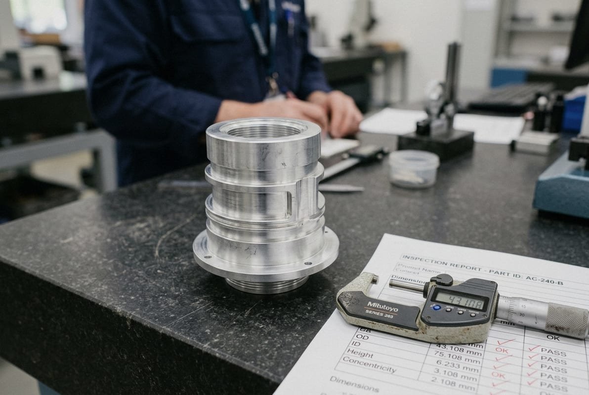
Cutting to spec is only half the job. Before any shipment leaves our facility, our QC team runs dimensional inspections and produces a full inspection report. For first articles, we provide FAI confirmation 6 with material certificates. This closed-loop process — program, cut, measure, confirm — is what turns high precision from a marketing claim into a documented fact.
Can I use CNC machining for a wide enough range of materials to meet my project specs?
Last quarter, a single client's BOM included 6061-T6 aluminum 7 housings, 316L stainless steel fittings, Grade 5 titanium pins, and PEEK insulator bushings — all machined in our Dongguan facility on the same row of machines.
CNC machining supports an exceptionally wide range of materials — from aluminum, stainless steel, brass, copper, and titanium to engineering plastics like ABS, POM, PEEK, nylon, and PPSU — giving most projects full material versatility without changing process technology.

Metals We Machine Daily
Aluminum alloys (6061, 7075, 2024) dominate our workload. They cut fast, hold tight tolerances, and accept anodizing well. Stainless steels (304, 316, 17-4PH) come next — harder on tooling but essential for medical, food, and marine applications. We also run brass, copper, alloy steels, tool steels, and titanium regularly.
Engineering Plastics
Plastics behave very differently under a cutting tool. Soft materials like HDPE and nylon can deform under clamping pressure. Brittle plastics like PMMA can chip. Our approach is to adjust spindle speed, feed rate, and coolant strategy for each polymer. PEEK and POM, for example, machine cleanly and hold dimensions well, making them popular for medical and semiconductor parts. For a deeper dive into choosing the right stock, see our guide on the best materials for precision CNC machining.
Material Selection Guide
| Material Category | Common Grades | Key Properties | Typical Applications |
|---|---|---|---|
| Aluminum Alloys | 6061, 7075, 2024 | Lightweight, corrosion-resistant, easy to machine | Housings, brackets, heat sinks |
| Stainless Steel | 304, 316L, 17-4PH | High strength, corrosion-resistant | Medical devices, food equipment |
| Titanium | Grade 2, Grade 5 | High strength-to-weight, biocompatible | Aerospace, implants |
| Copper & Brass | C110, C360 | Excellent conductivity, easy to machine | Electrical connectors, fittings |
| Gereedschapsstaal | D2, A2, S7 | High hardness, wear-resistant | Injection mold inserts, dies |
| Engineering Plastics | PEEK, POM, Nylon, ABS, PPSU | Chemical resistance, lightweight, insulating | Insulators, bushings, prototypes |
Where Material Limitations Appear
CNC machining is subtractive. The cutting tool must be harder than the workpiece. Extremely hard ceramics or certain superalloys push standard carbide tooling to its limits. Very soft materials — silicone rubber, for example — deform rather than cut cleanly. And thin-walled parts in any material risk vibration and distortion during machining. These are real boundaries.
When a material or geometry falls outside what CNC handles efficiently, we guide clients toward complementary processes. We operate an in-house injection mold division 8 specifically for this reason. Parts that are too thin, too soft, or too complex for CNC can shift to injection molding — and parts with volumes too low to justify mold tooling stay on CNC. This complementary approach covers more ground than either process alone.
What are the design limitations of CNC machining that might affect my part's manufacturability?
One lesson we learned early — and now teach every new client — is that a beautiful CAD model does not always translate into a machinable part. A European automation company once submitted a housing with 0.3 mm internal walls, deep narrow slots, and sharp 90° inside corners. Our DFM review flagged seven features that would either break tools or warp under cutting forces.
CNC machining struggles with extremely thin walls, deep narrow cavities, sharp internal corners, severe undercuts, and highly irregular organic shapes — because the rotating cutting tool has a fixed minimum radius, limited reach, and generates forces that can distort fragile features.
The Cutting Tool Is the Constraint
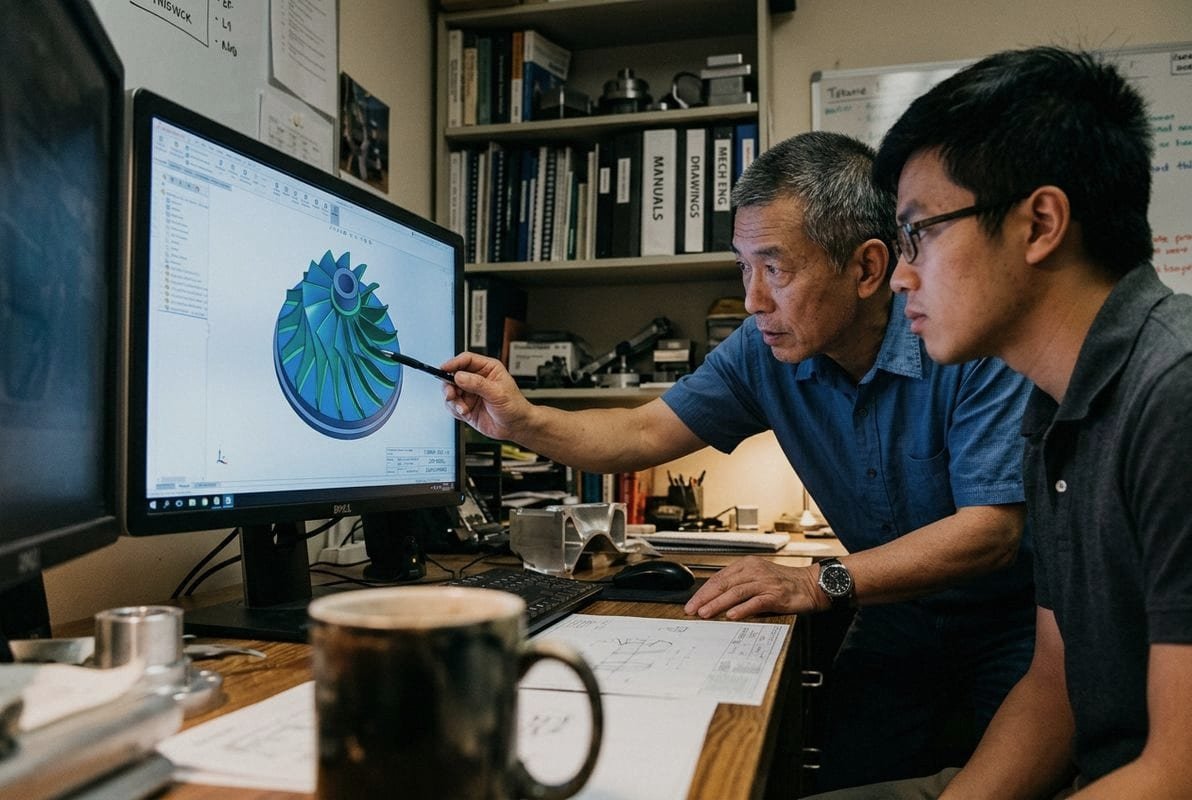
Every CNC end mill has a diameter. That diameter sets the smallest internal corner radius the machine can produce. If your drawing calls for a perfectly sharp 90° inside corner, the mill physically cannot create it without secondary operations like EDM. This is the single most common DFM issue we flag.
Tool length-to-diameter ratio also matters. A long, thin tool reaching deep into a pocket will deflect and chatter. We generally advise keeping pocket depth no more than four times the tool diameter. Beyond that, surface finish degrades and dimensional accuracy drops.
Thin Walls and Fragile Features
Thin walls vibrate under cutting forces. Aluminum walls below 0.8 mm and steel walls below 1.0 mm become risky. The part may pass inspection on the machine but warp after release from the fixture. We often suggest adding ribs or increasing wall thickness by just 0.2–0.3 mm to solve this without changing the part's function.
Common DFM Issues and Solutions
| Design Feature | Problem | Recommended Fix |
|---|---|---|
| Sharp internal corners (< R0.5 mm) | Tool cannot reach; stress concentration | Add fillet radius ≥ tool radius |
| Wall thickness < 0.8 mm (aluminum) | Vibration, warping, tool deflection | Increase to ≥ 1.0 mm or add ribs |
| Deep narrow slots (depth > 4× width) | Tool deflection, poor surface finish | Widen slot or reduce depth |
| Undercuts / internal features | Standard tools cannot access | Use Wire EDM or redesign |
| Very large flat surfaces | Warping during machining | Add slight draft or machine in stages |
| Organic / freeform shapes | Requires 5-axis; long cycle times | Simplify geometry where possible |
When CNC Reaches Its Limit, Molds Step In
Some parts are simply not suited for subtractive machining at scale. Very thin, complex, organic shapes with uniform wall thickness scream for injection molding. In our operation, we maintain both CNC and mold-making capabilities under one roof. If CNC cannot deliver a feature economically, our mold team evaluates whether tooling makes sense. If the volume is too low for mold investment, we push the design back through CNC with DFM adjustments. This back-and-forth between CNC and molding is one of the most practical advantages we offer clients.
Material Waste Is Real
CNC is subtractive. You start with a solid block and remove everything that is not your part. On a complex aerospace bracket, material removal can exceed 80%. For expensive metals like titanium, that waste adds real cost. Additive manufacturing (3D printing) avoids this by building up material, but it trades off surface finish and mechanical properties. Understanding this trade-off helps you choose the right process for each part.
How do I justify the higher cost of CNC machining for my low-volume production runs?
A medical device startup in the U.S. once asked us to quote 50 pieces of a stainless steel surgical guide. Their previous supplier quoted injection molding — but the $18,000 mold cost made no sense for 50 parts. We ran the job on CNC in eight working days at a fraction of that tooling investment.
CNC machining justifies its cost in low-volume production by eliminating mold tooling expenses, enabling fast turnaround as short as five days, supporting design iterations without retooling, and delivering production-grade quality from the very first piece — making it the most economical choice when volumes stay below several thousand units.
No Tooling Investment
Injection molding, die casting, and stamping all require custom tooling. That tooling can cost anywhere from $3,000 to $50,000 or more, depending on complexity. With CNC, the "tooling" is a digital program. Changing the design costs hours of programming, not weeks of mold modification. For prototypes, bridge production, and runs under a few hundred pieces, this difference alone tilts the economics toward CNC. For a detailed comparison of when each approach makes sense, read our guide on how to choose between CNC prototyping and mass production.
Speed to First Part
Our production lead times start at five days for standard parts. There is no mold design phase, no mold steel procurement, no trial shots. You send a 3D file, we run DFM, you approve the quote, and machining begins. This production efficiency matters when your product launch date is fixed or your assembly line is waiting on one missing component.
Cost Breakdown: CNC vs. Injection Molding at Low Volumes
| Cost Factor | CNC Machining (50 pcs) | Injection Molding (50 pcs) |
|---|---|---|
| Tooling / Mold Cost | $0 | $8,000 – $25,000 |
| Per-Part Cost | $25 – $80 | $2 – $10 |
| Total Cost (50 pcs) | $1,250 – $4,000 | $8,100 – $25,500 |
| Lead Time | 5 – 15 days | 30 – 60 days (including mold) |
| Design Change Cost | Reprogram (hours) | Modify mold (weeks, $$$) |
| Break-Even Volume | — | Typically 500 – 5,000 pcs |
The table makes it clear: below a few hundred units, CNC wins on total cost. Above a few thousand units, molding's low per-part price overtakes CNC's. The crossover point depends on part complexity, material, and mold cost.
Reduced Labor Costs and Automation
One operator on our floor supervises multiple CNC machines running simultaneously. Automation handles tool changes — our machining centers hold up to 30 tools in rotating carousels — and the machines run lights-out overnight. This reduced labor cost per part helps keep CNC competitive even as part counts grow. Skilled operators focus on setup, programming, and quality verification rather than manual cutting.
Maintenance Costs and the Long View
CNC machines do require regular maintenance — spindle service, way lubrication, coolant management, and periodic calibration. These maintenance costs are real and must be factored into pricing. But from the buyer's perspective, a well-maintained ISO 9001:2015 certified shop 9 absorbs these costs into stable, transparent per-part pricing. We do not surprise clients with hidden surcharges after quoting.
When to Consider Alternatives
If your volume crosses into the thousands and your design is stable, injection molding almost always costs less per piece. If your part is extremely large or uses very expensive material, additive manufacturing might reduce waste. And if your geometry is simple enough for traditional machining on a manual lathe, that can be cheaper for one-off pieces. CNC machining sits in the sweet spot between these extremes — capable of high precision, complex geometries, and production-grade quality without the heavy tooling commitment.
Conclusion
CNC machining offers high precision, material versatility, and speed without tooling investment — but every buyer must weigh its limitations in wall thickness, waste, and cost at scale to make the right manufacturing decision.
Footnotes
1. Replaced HTTP 403 with an authoritative Wikipedia page on Computer Numerical Control. ↩︎
2. Replaced HTTP 403 with an authoritative Wikipedia page on CAD/CAM. ↩︎
3. Replaced HTTP 404 with an authoritative Wikipedia page defining Polyether Ether Ketone (PEEK) polymer. The anchor text was adjusted for better relevance to the content of the replacement URL. ↩︎
4. Replaced HTTP 404 with an authoritative Wikipedia page explaining G-code. ↩︎
5. Details 5-axis CNC machining, explaining its axes and ability to create complex geometries. ↩︎
6. Explains First Article Inspection (FAI) as a process to verify manufacturing capability and part conformity. ↩︎
7. Replaced HTTP 403 with an authoritative Wikipedia page detailing 6061-T6 aluminum alloy properties. ↩︎
8. Explains the injection molding process, its steps, and applications for plastic parts. ↩︎
9. Official ISO page explaining ISO 9001:2015, a globally recognized quality management standard. ↩︎

 Nederlands
  English
  Italiano
  Français
  日本語
日本語  Deutsch (Sie)
  Español
  Русский
  العربية
  Български
  Čeština
  Dansk
Dansk  Suomi
Suomi  עִבְרִית
  हिन्दी
  Português
  Română
  Slovenčina
  Svenska
  ไทย
ไทย  Tiếng Việt
  Türkçe
  Slovenščina